Native ESP8266 BrewPi Firmware - WiFi BrewPi, no Arduino needed!

Homebrew Talk - Beer, Wine, Mead, & Cider Brewing Discussion Forum

Help Support Homebrew Talk - Beer, Wine, Mead, & Cider Brewing Discussion Forum:

This site may earn a commission from merchant affiliate links, including eBay, Amazon, and others.
It’s not all that different from BrewPi in that respect. Where it’s significantly different is that the web app is integrated with the "scripts" and served by nginix.
 
Last edited:
It’s not all that different from BrewPi in that respect. Where it’s significantly different is that the web app is integrated with the "scripts" and served by nginix.

I was never that familiar with BrewPi, just treated it as a black box. Now I'm more curious about what's going on under the hood.
 
I was never that familiar with BrewPi
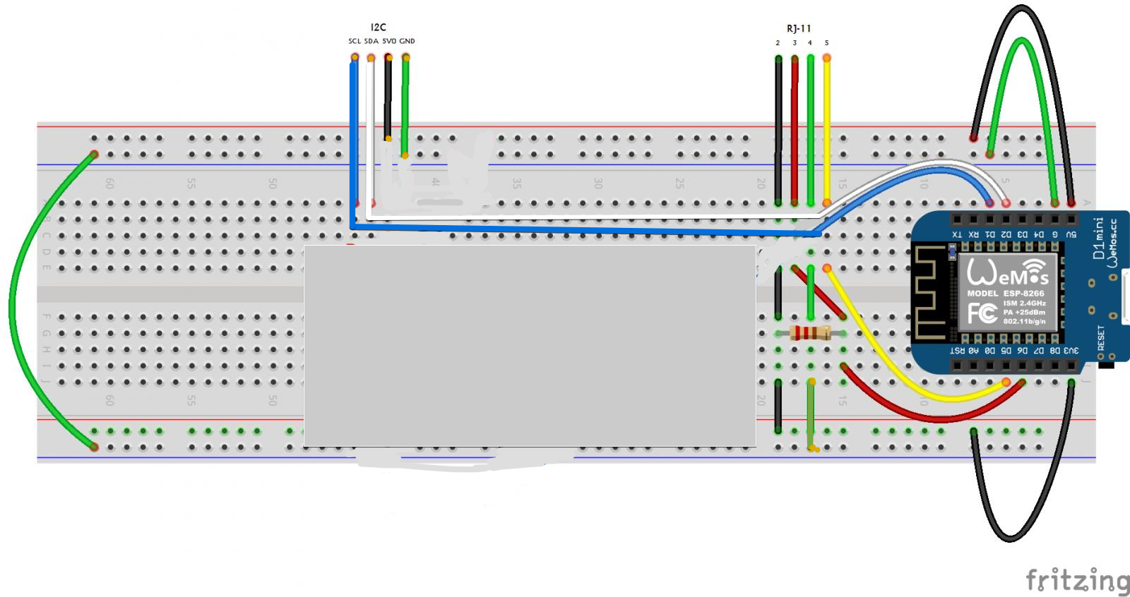
Dude, you did the wiring diagram that helped start the revolution! :D

Speaking of which ... where did you find the Fritzing (I assume you did it there) models for the probes?

BrewPi uses a socket connection to allow the Python script to open the serial port directly. The python script then creates/opens a socket through which the web server and the python script communicate. This is in part what allows information and commands to pass without www-data being a privileged user.

@Thorrak combined the script and web application in a manner I'm honestly not familiar with (Django is new to me) allowing "brewpi" to own everything as near as I can tell. Therefore the script still opens the serial port (or the representation of one via wifi - it's mostly all the same to python) and the web application is in the same security context allowing it to do jobs which are not possible in BrewPi currently.

A word of warning though - I subscribe to the "if you want the right answer, give the wrong one publicly" school of thought, so my interpretation of Thorrak's work is subject to review and connection. :) I'm pretty sure about how BrewPi itself works however.
 
Speaking of which ... where did you find the Fritzing (I assume you did it there) models for the probes?

I don’t think Fritzing was a thing back then. At least I didn’t know about it. I drew that stuff from scratch in Illustrator. I used to do technical illustration for electronics and musician mags in a previous life.

Look closely, the Arduino is only partially populated with components (I’m lazy) and it has my initials TAJ in one corner. I even drew the UNO logo.

I’m an (old) analog electronics guy, so this stuff is outa my comfort zone, but fun and fascinating as hell. Like brewing. I wish I knew enough to contribute more.

Thanks for the architecture details, Lee.
 
I had to do a search ( Note: there is a correction the diagram in the next couple of posts)
https://www.homebrewtalk.com/forum/...troller-for-cheap.466106/page-35#post-6312976

Apparently I updated the diagram at some point. The one fuzzewuzze shows in post #1 of his DIY brewpi thread is the newer one. Circuit ground is lifted from power ground, so the GND reference will come from the rpi (or the laptop in my case) over USB.

Now, back to the present topic...
 
Last edited:
So things were going fine..........then my DSL line and telephone crapped out Telco decided I needed a new router. Finally got Fermentrack up and running but can't flash my mini so as to give it the new wifi. Suggestions?
 
So things were going fine..........then my DSL line and telephone crapped out Telco decided I needed a new router. Finally got Fermentrack up and running but can't flash my mini so as to give it the new wifi. Suggestions?

Can you see it in AP mode on your available wifi devices?
 
First off thank you very much for the hard work on this awesome tool!
This is my first attempt at brewpi or similar so its been a hell of a learning curve.
So i've built a temp controller with a raspberry pi 3b+ and a wemos d1 mini.
Mostly working as should I think.

First problem I have is the LCD. As the weather was crap yesterday and I'm impatient I went to the local jaycar (I'm in country western australia so options are limited) rather than wait for the slow boat from china.
Apart from costing a small fortune I got most of what I needed. The LCD was this one
https://www.jaycar.com.au/dot-matrix-white-on-blue-lcd-20x4-character/p/QP5522
and this
https://www.jaycar.com.au/i2c-port-expander-module-for-lcd/p/XC3706
All I get is 2 lines (1 and 3) of solid blocks
I am using this level converter which looks the same as the sparkfun one
https://www.jaycar.com.au/arduino-compatible-logic-level-converter-module/p/XC4486

I have also just received an ispindel and was wondering you can assign the temp from the ispindel to the beer temp of the controller?

Thanks again

That LCD/Backpack combination should work, but the symptoms you noted are what I would expect if it wasn't receiving a signal. As you referenced, these LCDs run on 5v while the LoLin D1 Mini runs on 3.3v, so you need to use the logic level converter - can you recheck to make sure that the signals coming from the D1 mini go to the LV side, and the LCD is on the HV side? Additionally, can you recheck that the backpack is on correctly (it should be entirely contained within the footprint of the LCD, not rotated so that the backpack is above the LCD)? Is the controller otherwise working? What firmware did you flash to the board?


To the iSpindel question, the answer is no. The iSpindel only reports temperature every couple of minutes to save battery, but the BrewPi temperature algorithm is designed to control temperatures by running power for a certain number of seconds. The lack of real time temperature feed creates issues in the algorithm.
 
Thanks very much for the reply.
The backpack is fully contained within the footprint so i think i got that right. There are no solder shorts but my eyes aren't the best anymore and there could be a dry joint or two. I'll probably re flow the joints.
The pins from the d1 mini are going to the LV side and the LCD is on the HV side.
The controller seems to work just fine but i am yet to add relays and temp probes.
I used fermentrack to flash 0.11 wifi to the controller.

And that makes sense with the ispindel. Thanks heaps

Unfortunately, I don't have much more in terms of advice for this one. :( It sounds like you did everything correctly, but for some reason either the LCD, the backpack, or the level shifter aren't doing their job. Here I would normally say "try another LCD/backpack" but given yours is on a slow boat from China, that advice doesn't sound like it would be too helpful.

If it is any consolation, the LCD is completely optional, as Fermentrack displays the exact same thing that it should show. You should be able to build the rest of your controller & play with it while waiting on the LCD to arrive. Again - not ideal, but unless it's a bad solder joint, I can't think of any other options! :(
 
Not really. I mean it’s possible to mount a Linux partition on a PC, then stand up the database .... honestly it’s not trivial and I would expect it would take: 1) the data being recoverable and 2) someone that was familiar with the process a few hours if it was recoverable.

My opinion is it would be easier/quicker/more sure to start over.

This is why we always recommend people get good backups regularly and never power off the Pi without shutting it down.

To second this, one of two things are likely true:

If the SD card is mostly OK, and just system files are corrupted, then as long as you have a separate SD card (to install a new system), have an SD card reader (to attach the old card), and are comfortable with using the command line, it may be recoverable. You would mount the old SD card using the reader to a folder on the new install and could copy the files off.

If the SD card is really corrupt, however, it’s going to be more trouble than it’s worth.
 
Hello everyone. I set up my fermtrack set up about a year ago. It was up and running and awesome and then life got in the way for the last year. Long story short, I have changed my wifi router (my old one had terrible coverage so i upgraded). How do switch over my devices to the new router?
 
To second this, one of two things are likely true:

If the SD card is mostly OK, and just system files are corrupted, then as long as you have a separate SD card (to install a new system), have an SD card reader (to attach the old card), and are comfortable with using the command line, it may be recoverable. You would mount the old SD card using the reader to a folder on the new install and could copy the files off.

If the SD card is really corrupt, however, it’s going to be more trouble than it’s worth.
You could just set the name/password as the same as your old router. Easiest thing to do.
 
Hi guys, Firstly I apologise for asking this question if its already been covered somewhere in this thread. I am still only half way through it.
Ive just installed Fermentrack on my raspberry pi and have it working well with Ispindel and now am attempting a brewpi temp controller.
Ive got it setup on a bread board and can see it in Fermentrack no problems as a new device but I cant get the display to work on the LCD screen. If I adjust the potentiometer on the Ic2 board I just get black squares and thats it.

Any suggestions on what I can try would be much appreciated.
 
Ive just installed Fermentrack on my raspberry pi and have it working well with Ispindel and now am attempting a brewpi temp controller.
Ive got it setup on a bread board and can see it in Fermentrack no problems as a new device but I cant get the display to work on the LCD screen. If I adjust the potentiometer on the Ic2 board I just get black squares and thats it.
When you say a "brewpi temp controller" what do you mean? An ESP8266 or an Arduino?
 
When you say a "brewpi temp controller" what do you mean? An ESP8266 or an Arduino?
A Wemos d1cMini.. ESP8266. I flashed it with the node Mcu firmware but it changed the SSID to ESP_67EBE6 and I had trouble trying to connect to it to configure wifi.
So I reflashed it with the default firmware in fermentrack and can see it no problem. But the LCD screen doesn’t work.
I ran a sketch to see if it detected the screen and received an error saying no I2C detected.
 
So I double checked the connections and they are all ok. I doubt the LCD is faulty (Although if I do buy another one and it doesn't work either its getting costly)
I don't have the relay board or temp sensors yet and this is just setup on a bread board but I assume that the lcd should still work without them.

Anything else I can try? Im very new to all this and it took me most of last night just to work out how to add a sketch and check if it detects the screen.
 
I had the same problem and had to upgrade my power supply and up the voltage to 9v. I am using one of thorrak's PCB. I now power the pcb with a 5v phone charger and have no problems- (Not counting the time the dog peed on the RPI0 and shorted it out.)
EDIT: Power supply
I went and looked at my set up. I have the RPI0W running off the 5v phone charger and the ESP8266 and stuff running off 9v plugged into the power supply of Thorrak's PCB.
 
Last edited:
Try using the LCD straight to the board:

GND - GND
3v3 - VCC
D2 - SDA
D1 - SCL
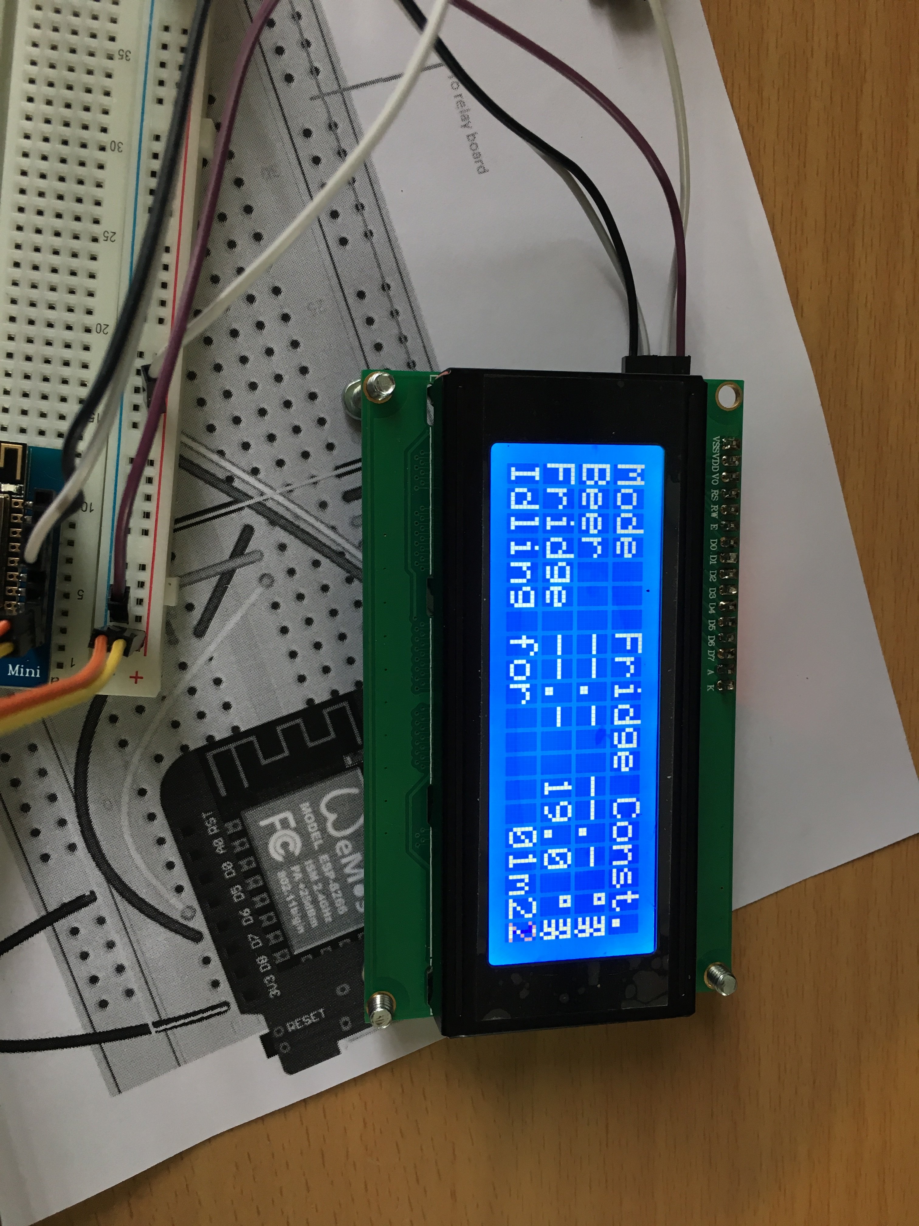
So with 3V it was very faint so I plugged it into 5V and it works. So does that mean I don't need the level convertor?

Im using this one

https://www.jaycar.com.au/arduino-compatible-logic-level-converter-module/p/XC4486

43BA83B0-2A34-451C-907E-C55BFF8F7572.jpeg
 
Also why is my Celcius symbol incorrect? Is that because I don't have temp probes connected yet?
 
I had the same problem using the level shifter and lcd not working. Going direct has solved the problem for me also.
Another problem though i can't get the temp probes to read. When i go to configure sensors/pins in fermentrack i have chamber sensor and beer sensor not set but have no place to set them. I only have the heating pin cooling pin and door pin available to set.
Any pointers?
Cheers
 
How certain are you that your probes are not ds18b20-PAR (parasitic) models?
That has screwed lots of folks over the last few years...

Cheers!
 
Well the ad certainly leaves one presuming the probes are wired for non-parasitic operation.

I've never received a ds18b20 with any labeling on the probe or wire, so one is left with testing.
Someone posted a Arduino script that can tell whether a probe is parasitic or not.
You'll find it in a post of mine here. I'd love to credit the author but I have no idea who wrote it...

Cheers!
 

Latest posts

Back
Top