Native ESP8266 BrewPi Firmware - WiFi BrewPi, no Arduino needed!

Homebrew Talk - Beer, Wine, Mead, & Cider Brewing Discussion Forum

Help Support Homebrew Talk - Beer, Wine, Mead, & Cider Brewing Discussion Forum:

This site may earn a commission from merchant affiliate links, including eBay, Amazon, and others.
#include <OneWire.h>
#include <DallasTemperature.h>
#define ONE_WIRE_BUS 18
OneWire oneWire(ONE_WIRE_BUS);
// Pass our oneWire reference to Dallas Temperature.
DallasTemperature sensors(&oneWire);
void setup() {


Serial.begin(9600);
sensors.begin();
}
void loop() {
Serial.print("Parasite power is: ");
if (sensors.isParasitePowerMode())
Serial.println("ON\n");
else
Serial.println("OFF\n");
Serial.print ("Detected ");
Serial.print(sensors.getDeviceCount(), DEC);
Serial.print(" devices\n");
byte deviceAddress[8];
for (int i = 0; i < sensors.getDeviceCount(); i++) {
sensors.getAddress(deviceAddress, i);
Serial.print("Device ");
Serial.print(i);
Serial.print(" is a ");
switch (deviceAddress[0]){
case DS18S20MODEL:
Serial.print("DS18S20\n");
break;
case DS18B20MODEL:
Serial.print("DS18B20\n");
break;
case DS1822MODEL:
Serial.print("DS1822\n");
break;
case DS1825MODEL:
Serial.print("DS1825\n");
break;
default:
Serial.print("Unknown\n");
}
}
delay(1000);

sensors.requestTemperatures(); // Send the command to get temperatures
delay(750);
for (int i = 0; i < sensors.getDeviceCount(); i++) {
float temp = sensors.getTempCByIndex(i);
Serial.print ("Sensor ");
Serial.print (i);
Serial.print (" ");
Serial.print(temp);
Serial.print("\n");
}
Serial.print("\n");
}
 
Ok so does this updated wiring diagram look correct?
It does, although to keep things even simpler you can use 5V for the RJ11/45 and there's no reason you can't use a 4K7 resistor for that.

I'm going by memory, but I think the 3V LEDs were quite a bit cheaper at the time. That may have changed.

Not sure where you got your original drawing but in later board designs, @Thorrak went to an RJ45 for the connections. The reason being is Ethernet cables are always straight through and phone cables have a crossover design. It is simpler to use the RJ45 even though in his design he does not use those pins.
Also why is my Celcius symbol incorrect? Is that because I don't have temp probes connected yet?
No, that's likely a bad display. His firmware resets the LCD every 180 seconds so if it's still wrong there's likely something wrong with the LCD. If you want to test, find a "Hello World" sketch and modify the text to fill the screen. This one from Random Nerd Tutorials will get you there. It's written for the ESP32 but he has notes for the ESP8266 as well. When you get to the part where you set the variables in the sketch, make sure you use int lcdRows = 4;. Other than that I believe you can modify the display text pretty easily and figure you if you have an LCD problem.
 
I'm going by memory, but I think the 3V LEDs were quite a bit cheaper at the time. That may have changed.
It does, although to keep things even simpler you can use 5V for the RJ11/45 and there's no reason you can't use a 4K7 resistor for that.
No worries will remove the 3v connection. What 3V LEDs are you referring to?

Not sure where you got your original drawing but in later board designs, @Thorrak went to an RJ45 for the connections. The reason being is Ethernet cables are always straight through and phone cables have a crossover design. It is simpler to use the RJ45 even though in his design he does not use those pins.

the drawing was from earlier posts in this thread. I wasnt going to use any RJ conection at all and just hard wire the sensor wires. Do you recommend I use the RJ45 connections? Dont I need an ethernet crimping tool to connect them up?

No, that's likely a bad display. His firmware resets the LCD every 180 seconds so if it's still wrong there's likely something wrong with the LCD. If you want to test, find a "Hello World" sketch and modify the text to fill the screen. This one from Random Nerd Tutorials will get you there. It's written for the ESP32 but he has notes for the ESP8266 as well. When you get to the part where you set the variables in the sketch, make sure you use int lcdRows = 4;. Other than that I believe you can modify the display text pretty easily and figure you if you have an LCD problem.

The Celsius symbol is working now. I added the blink sketch at one stage to test the board but had no idea how to remove it again and had to wipe the firmware. how do you actually remove a sketch? The instructions said go HIGH or soemthing but I had no idea what that meant.

Thanks heaps for all your help with this. Much appreciated.
 
No worries will remove the 3v connection. What 3V LEDs are you referring to?
That was a typo - I meant LCD.
the drawing was from earlier posts in this thread. I wasnt going to use any RJ conection at all and just hard wire the sensor wires. Do you recommend I use the RJ45 connections? Dont I need an ethernet crimping tool to connect them up?
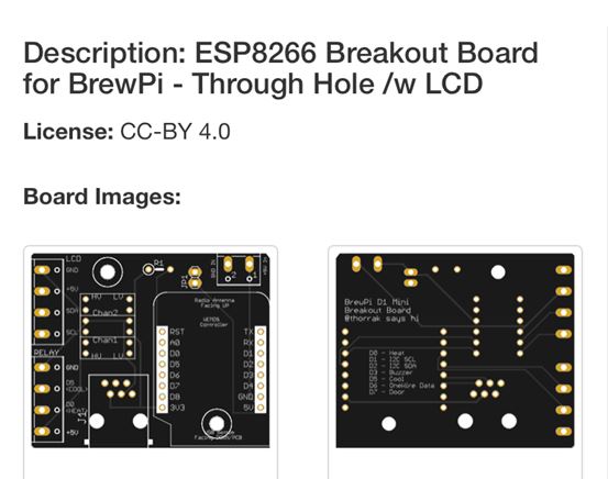
The idea is you use a PCB for the ESP-8266 coupled with a breakout board both listed on this page. Then you can use a commercially purchased Ethernet cable to connect the two, and the breakout board would use either screw terminals or DuPont connectors depending on your preference.

(Edit: I've removed the discussion about removing the level shifter till we figure all that out.)
 
Last edited:
That was a typo - I meant LCD.

The idea is you use a PCB for the ESP-8266 coupled with a breakout board both listed on this page. Then you can use a commercially purchased Ethernet cable to connect the two, and the breakout board would use either screw terminals or DuPont connectors depending on your preference.

The challenge there is that ESP-8266 board has a built-in level shift so you can't use it with your LCD. I've attached an updated ESP-8266 board design which uses an RJ-45 and no level shifter. (@Thorrak please feel free to snag this and use it if you like, more and more the I2C LCD's are 5V.)

You just flash it with a new sketch (i.e. the Blink sketch or something). When you flash the regular firmware, you remove the old one.

Ive ordered this board here. I only ordered it on Friday though so Im wondering if I can change to the one you have listed.

What SMD components are on the board as Whilst Im confident to solder normal sized components Im not that confident in doing SMDs.

PCB ORDer.JPG
 
Last edited:
Actually I see what you mean the board I ordered has to use the level convertor. The board you suggested doesnt need the level convertor and has an RJ45 connector.

So I suppose I need to see if @Thorrak will cancel my order and send this board out instead?
Ive replied to my order email asking him if he can do this.
Thanks again.
 
Last edited:
Thorrak doesn't actually make those boards, he just designed them and gets a couple cents credit for his boards (you go through a lot when you do this) when you buy through his link.

Let me have a look at that design here in a little bit, Might be as easy as a few jumpers.
 
E27FB5CF-2931-4EC7-8B86-B4A510F801C0.jpeg
Problem: esp8266 I/O are not 5V tolerant.
Regardless of ohms, that pull-up needs to be on the 3.3V rail...

Cheers!
Thanks @LBussy. I will modify the board when it gets here. But what your saying @daytrippr is that the temp sensors need to be connected to 3.3V? I tried it with 5v. But a 10k resistor as that’s all I had.

It showed 19C on the fridge temp. But it showed that with no sensor connected anyway. But the beer temp wouldn’t display.
 
Last edited:
I'll re-draw it either this evening or tomorrow making the sensor 3V3.
Ok so when wiring this up on the bread board for testing I connect the sensors to 3V3 but what about the data wires?

Ive seen 2 different wiring diagrams. One where they are joined together and then go to D6 (And 10K resistor is bridged across them to the power lead).

Then the heating and cooling lines come from the relay to D5 and D0.

And another diagram where the data wires are kept seperate. One goes to D6 marked Onewire and the other goes to D5 marked door. The 10K pull up resistor is connected across the D6 lead and 3v3.

Which one is correct?
 
Apologies for injecting confusion but when this sub-thread began I didn't realize which topic I was in and that the controller in question was an ESP8266, and instead thought an Arduino was involved. So many BrewPi and spin-off threads, plus I have a ton of distractions this week.

My bad.

To use a 5V I2C LCD with any ESP, the level convertor needs to be used. This is because the LCD backpack provides 4.7K pull-ups for SCL and SDA - that go to 5V (reference R8 and R9 on the commonly used backpack). So the LCD should get 5V/GND and the up-shifted outputs from the level convertor.

As for the temperature sensors, I've only ever run my ~two dozen+ ds18b20s on 5V with pull-ups to 5V on all of my Arduinos. I haven't even tried running them on 3.3V with a 3.3V pull-up so you're on your own on that one.

Bottom line is whatever hits the ESP needs to conform to 3.3V signalling. If the probes don't like running on 3.3V, try powering them on 5V but keep the pull-up on 3.3V and see what happens. This works on Raspberry Pi's just fine, but I expect that would require some re-work to that board...

Cheers!
 
Last edited:
To use a 5V I2C LCD with any ESP, the level convertor needs to be used.

Thanks very much for your help.

I tried the LCD first with the level convertor and it would light up but not display any characters. I then bypassed the level convertor and now it works.

As for the temperature sensors, I've only ever run my ~two dozen+ ds18b20s on 5V with pull-ups to 5V on all of my Arduinos. I haven't even tried running them on 3.3V with a 3.3V pull-up so you're on your own on that one.
I tried them on 5V and didnt get a reading.

Bottom line is whatever hits the ESP needs to conform to 3.3V signalling. If the probes don't like running on 3.3V, try powering them on 5V but keep the pull-up on 3.3V and see what happens.

Im not sure what you mean here. How do I power them with 5V but keep the pull up on 3.3V. Are you able to do a wiring diagram as Im not quite sure what you mean? Thanks again for your help.

EDIT:- No all good I get it now resistor goes from 3.3V on the WEMOS across to the data line that goes into D6 on the WEMOS
 
Last edited:
@day_trippr beat it into my head enough so that I'm following, so I'll repay his patience by trying to help you.

Level shifter is necessary, so if your circuit did not work it's likely one of two things happened:
  1. Your wiring had an error
  2. Your level shifter is bad
The easy way through this therefore is to wire it up with the level shifter again. See what happens. If it does not work, take a good pic and post it and we can see if we note an issue. One thing at a time though - just the controller and the LCD. Leave the probe(s) out for now.
 
[...]
EDIT:- No all good I get it now resistor goes from 3.3V on the WEMOS across to the data line that goes into D6 on the WEMOS

Right. That would stay as writ.
Maxim says the ds18b20 works with VDD and pull-up voltages both anywhere from 3.0 to 5.5 volts (so that's theoretically 10% margins at either end). I just can't vouch for the former.

I don't know why your LCD didn't work with the level shifter in place, but my guess would be a miswire or bad translator, because it should work.

Cheers!
 
Thanks guys, Will tackle it with the level shifter and LCD only tonight when I get home from work.
 
This is the wiring diagram I followed originally and only had black squares on the LCD. The level shifter was brought brand new from Jaycar (not Chinese ebay crap). I have a mate on Aussie Home brewer who also wired his up the same way using the same level convertor from Jaycar and he had the same issue. So unless Jaycar have a bad batch of these things that were sold Australia wide (He lives in West oz Im in Victoria) which isnt likely. Then the wiring diagram has to be wrong. I dont think we would both get it wired incorrectly. I re did mine 3-4 times and checked it again each time.

Any thoughts on this wiring diagram as Im stumped now????

ESP8266 BrewPi_bb.jpg
 
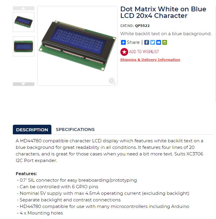
This is the LCD I brought and I soldered on the XC3706 I2C port expander. (Which Ive double checked for good solder connections, no shorts etc.
LCD Jaycar.JPG
 
Thank you!
I'll have a crack at that shortly.
How did you go with this as Ive brought the same probes from the same supplier and this will be my next issue down the track. What exactly does parasitic mean anyway?
 
It is said that ESP8266 is 5v tolerant. I have an I2C LCD connected directly to ESP8266 for over 2 years.
 
Right. That would stay as writ.
Maxim says the ds18b20 works with VDD and pull-up voltages both anywhere from 3.0 to 5.5 volts (so that's theoretically 10% margins at either end). I just can't vouch for the former.

I don't know why your LCD didn't work with the level shifter in place, but my guess would be a miswire or bad translator, because it should work.

Cheers!
Would the 'backpack' board on the LCD be different to what you get from a complete board from aliexpress or where ever?
Here is the data sheet for the jaycar one. Not sure if I'm reading it correctly but says it can take from 2.5v to 6v?

https://www.jaycar.com.au/medias/sys_master/images/9264412753950/XC3706-dataSheetMain.pdf

Still not sure why it doesn't seem to work after level converting to 5v though
 
That spec is strictly limited to the pcf8574 8 bit I2C expander. It does not include everything else - like the LCD module, which is crammed with things like static ram, decoders, and display drivers.

There's a myriad of msi components available today with VDD as low as 1.2 volts (indeed, many of my commercial designs depend on them) but then there's the whole plethora of components that still need 5V to operate. These inexpensive ($8-10 if you are willing to wait on Far Eastern shipping) aren't pushing the technology envelope.

With respect to whether esp8266 IO are "5v tolerant", if you look at the spec there's the claim that a "snap back" circuit provides protection up to 5.8V sustained. However, if one spends some Google time it becomes evident there are numerous claims that ExpressIO recommends not testing that circuitry and stick with 3.3V signalling.

I don't like killing stuff out of convenience. It's pretty much anathematic to me considering much of my career was spent designing fault tolerant servers with 5 to 6-nines availability ;) That said, esp's are cheap (very much unlike those servers) so if one wants to tread that path the downside isn't all that punitive...

Cheers!
 
Glad you got it working - how did you end up wiring it?

The thing about the Internet is for any given choice you can find someone to tell you it's fine. That does not necessarily mean it's the right choice. It just means that some moron on the Internet (me included) who doesn't have to pay for your stuff, decided he or she didn't care what you do. So, what happens if you use 5V on the ESP8266? Well, obviously nothing at least some of the time. But, what happens if/when the thing gets tired of you not believing your data sheet? Do you end up cooking an expensive batch of beer while you think it's controlling the fridge?

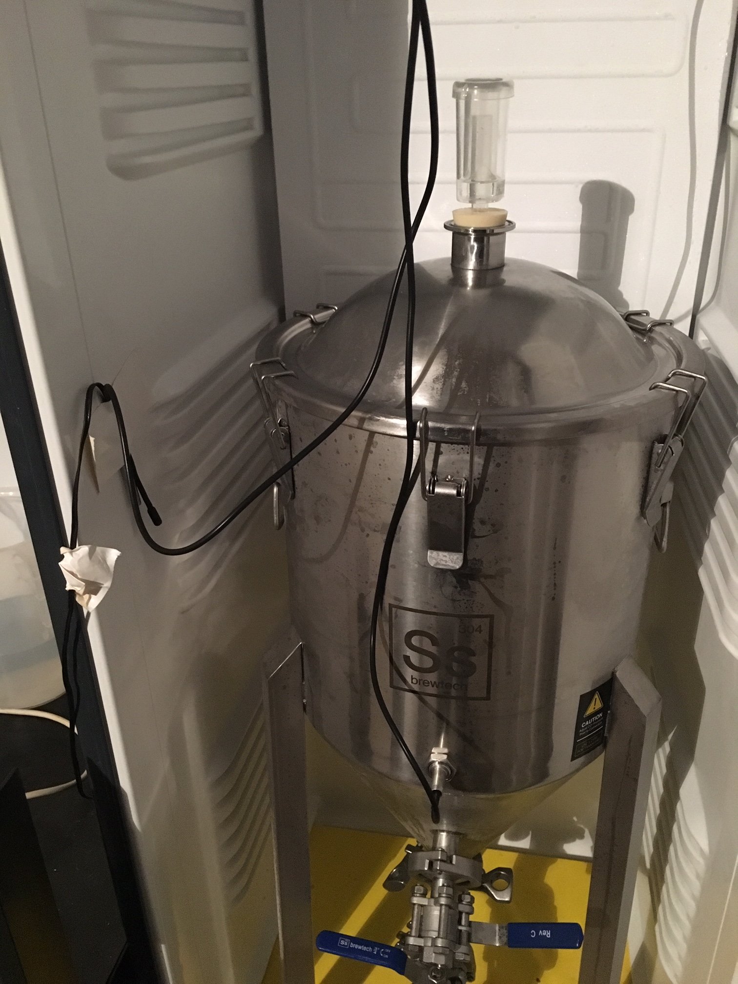
Some tips for you given your pic above:
  • Position the chamber probe in free air where it cannot touch anything else. If you look at this 3D design, one of the pieces is a little bracket @gromitdj created for that purpose. Obviously anything can be used, but that's just an idea for you.
  • Make sure the fermenter is not touching the evaporator in the back. Strange things will happen (don't ask how I know.)
  • Use a fan 100% of the time inside the chamber. It helps a TON getting and keeping stable readings.
Good luck!
 
On the BrewPiLess they're using a 4.7k ohm resistor between DATA (D6) and VCC (3V3), on the BrewPI it's using a 10k ohm resistor on the single wire temp sensor. Can I wire the BrewPi to work like the BrewPiLess and does it work best with 3V3 or 5V? Thanks.
 
It is wired the same way - just using a different resistor. The 10k consumes less power so in theory it's a better choice provided it works; and it apparently does as there's a lot of boards in use.

Not really sure what you're trying to do/accomplish.
 
I'm trying to create a board that will work for either BrewPiLess or BrewPi and I'm trying to standardize the temp sensor, since on each project it's wired differently.

I just want to make sure that if I run it the way BrewPiLess does with the 4.7k ohm resistor that it will work on BrewPi. Thanks.
 
I just want to make sure that if I run it the way BrewPiLess does with the 4.7k ohm resistor that it will work on BrewPi.
Can't speak to how you can create The One Board™ but yes, 4k7 will work with the ESP-8266 BrewPi. I would imagine the 10k would work with the BrewPiLess as well.
 
Can't speak to how you can create The One Board™ but yes, 4k7 will work with the ESP-8266 BrewPi. I would imagine the 10k would work with the BrewPiLess as well.

Awesome, I'll test both (4.7k and 10k) once I get my prototype built! I wanted a board where I could have everything AIO (Wemos, Relays and Temp Sensor). Maybe not the One Board™ but it will be close to it....after many revisions....lol
 
Glad you got it working - how did you end up wiring it?

The thing about the Internet is for any given choice you can find someone to tell you it's fine. That does not necessarily mean it's the right choice. It just means that some moron on the Internet (me included) who doesn't have to pay for your stuff, decided he or she didn't care what you do. So, what happens if you use 5V on the ESP8266? Well, obviously nothing at least some of the time. But, what happens if/when the thing gets tired of you not believing your data sheet? Do you end up cooking an expensive batch of beer while you think it's controlling the fridge?

Some tips for you given your pic above:
  • Position the chamber probe in free air where it cannot touch anything else. If you look at this 3D design, one of the pieces is a little bracket @gromitdj created for that purpose. Obviously anything can be used, but that's just an idea for you.
  • Make sure the fermenter is not touching the evaporator in the back. Strange things will happen (don't ask how I know.)
  • Use a fan 100% of the time inside the chamber. It helps a TON getting and keeping stable readings.
Good luck!

I connected the probe to 3v3 and used a 4k7. One thing I didnt realise is that you have to setup the probes in Fermentrack first before they will display properly on the LCD screen. But works great now.

Thanks for the help and extra tips on all of this, much appreciated. My ferm chamber is an all fridge so no fan inside. What type of fan would be suited?
I was thinking of mounting a CPU fan below the platform that the fermenter sits on facing the door as there is about a 2 inch gap and it would blow air against the door which would rise up into the main chamber.
I have a light that is covered with a metal plate that I use for heating so would put this below the chamber and the fan would draw the heat up into the top as well.

How does the chamber probe work in conjunction with the fermenter probe? Does it try to average out the temp on both of them?

Thanks again.
 
Anything that moves air around will work. I have a little desk fan in my fridge and that's probably way more than I need. I'm sure a CPU fan would be great.

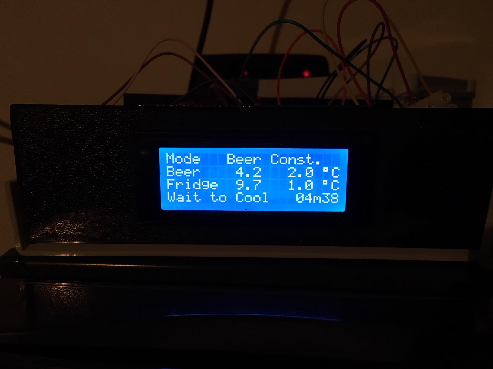
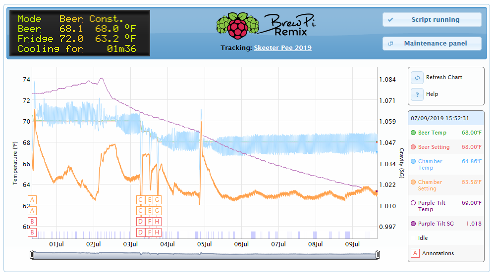
When BrewPi is controlling beer temp, it uses the cooling (or heating) demand to set a chamber temp and then the chamber sensor to control that temp. So, completely made up but let's say the beer is 2° high; the chamber gets set 10° lower. If the beer is 4° high the chamber gets set to 15° lower. Once the chamber gets to the temp that is set by the controller, the fridge (or light) shuts off. That's how a control loop works in a real rough fashion.

Beer temp <> Chamber temp. Right now my fermenter is running about 4° warmer than the chamber - that's because fermentation causes heat and the chamber needs to be cooler to account for it.

upload_2019-7-9_16-16-59.png


(ETA: Excuse posting a different flavor here, it's all I had to demonstrate my point.)
 
Last edited:
I'm trying to create a board that will work for either BrewPiLess or BrewPi and I'm trying to standardize the temp sensor, since on each project it's wired differently.

I just want to make sure that if I run it the way BrewPiLess does with the 4.7k ohm resistor that it will work on BrewPi. Thanks.
Thorrak's boards will run both BrewPiLess and BrewPi. You need a special version of BrewPiLess to account for the different pin assignments. If I recall correctly the reason Thorrak used a 10k pull-up resistor is that's what he had on hand.
 
Anything that moves air around will work. I have a little desk fan in my fridge and that's probably way more than I need. I'm sure a CPU fan would be great.

When BrewPi is controlling beer temp, it uses the cooling (or heating) demand to set a chamber temp and then the chamber sensor to control that temp. So, completely made up but let's say the beer is 2° high; the chamber gets set 10° lower. If the beer is 4° high the chamber gets set to 15° lower. Once the chamber gets to the temp that is set by the controller, the fridge (or light) shuts off. That's how a control loop works in a real rough fashion.

Beer temp <> Chamber temp. Right now my fermenter is running about 4° warmer than the chamber - that's because fermentation causes heat and the chamber needs to be cooler to account for it.

View attachment 634849
Cheers mate, thanks for that. I get it now.
 
Resistors around 5k is recommended in the specification of DS18B20.
I was told that you even don't need it when using Arduino. However, the resistor is needed for ESP8266, as I was told.
 
If one enables the input pull-up function on an Arduino pin it may indeed work. But according to typical AVR specs the pull up value ranges from 20kΩ to 50kΩ, so the functional scope may be insufficient for some usage models.

Wrt esp8266, the equivalent invokable internal pull up ranges between 30kΩ and 100kΩ. That range may have even more limited applicability on One Wire interconnects.

The strength of the pull up ideally accounts for capacitive loading, which increases with the number of sensors and their cable type/length for a given One Wire topology. A single sensor on a short leash may work using the internal pull up alone, while multiple probes on long wires usually requires a lower value resistor to keep the low-to-high transition time reasonable with a monotonic DVDT.

fwiw, I rarely rely on internal pull ups. I prefer to have complete control over such functions...

Cheers!
 

Latest posts

Back
Top