Low bucks motorized grain mill

Homebrew Talk - Beer, Wine, Mead, & Cider Brewing Discussion Forum

Help Support Homebrew Talk - Beer, Wine, Mead, & Cider Brewing Discussion Forum:

This site may earn a commission from merchant affiliate links, including eBay, Amazon, and others.
Little update, finally got my mill/weigh station all set up. It is a 2x12 box that was scavenged from an old project. I can place two buckets underneath. I really like having the scale on the side as well. Wired in a switch on the atx itself and mounted to the side of the cart. I ran the wire through the top by the motor and along the underside, then out the side. Everything is sleek and most of it I had lying around. Has been working great, but did have the motor seize up on me once. I think it was a stick or rock, but flipped it on and off a few times and away it went. The most I have done was 35 lbs at one go, motor got pretty hot, forgot to measure temp. I think next time I may give it a few minutes in between to cool down. One of these days I'll get around to pulling the plastic off the mill casing!

2015-02-03 18.33.09.jpg


2015-02-03 18.36.54.jpg
 
So I ordered the car seat motor and it arrived today. The other components are all still on order. I have a question about the controller, though. Is it required? I briefly test-hooked up the motor to a 12-volt battery and it spun just fine. I reversed the leads and it spun the other direction. What exactly does the controller do for you?
 
So I ordered the car seat motor and it arrived today. The other components are all still on order. I have a question about the controller, though. Is it required? I briefly test-hooked up the motor to a 12-volt battery and it spun just fine. I reversed the leads and it spun the other direction. What exactly does the controller do for you?

In addition to an on/off/on switch ( for direction control ) it also gives you speed control and voltage regulation. The last two probably aren't critical for this application as you'll probably want to run full speed most of the time and the motor appears to be rugged enough to handle the occasional voltage spike. I suppose I was being overcautious when I put mine together, when you work with electronics everyday you tend to do that!
 
is there any consensus as to what power supply to use? the amazon power supply has a few bad reviews pertaining to the power supply overheating or not putting out the 6 amps claimed. i want to order a motor and give this a shot since the total money invested is so low and it looks like a couple of guys on here have made it work.
 
is there any consensus as to what power supply to use? the amazon power supply has a few bad reviews pertaining to the power supply overheating or not putting out the 6 amps claimed. i want to order a motor and give this a shot since the total money invested is so low and it looks like a couple of guys on here have made it work.

When I switched from the AC motor to the DC motor I tried a 3 amp power supply which was not enough power, I then hooked up a 30 amp power supply which worked great. Spellman used an PC ATX power supply on his set up but I don't think we ever determined the minimum amperage/wattage needed.
ATX power supplies go for about $15 and up on Amazon.
 
A car seat motor...... Brilliant!!

They have enough torque to move fat people in their seats, I imagine they have enough torque for a mill.

And I can get plenty of them from work, I have replaced several seat frames recently because of occupancy sensor failures.
 
Cool project for a low budget option. A permanent motor for the mill (as opposed to dragging out the drill every time) is another step in reducing brew day frustrations.
 
When I switched from the AC motor to the DC motor I tried a 3 amp power supply which was not enough power, I then hooked up a 30 amp power supply which worked great. Spellman used an PC ATX power supply on his set up but I don't think we ever determined the minimum amperage/wattage needed.
ATX power supplies go for about $15 and up on Amazon.

Cool, I have a power supply I knew would come in handy someday, it only took almost a decade but the time has come to dust it off.
 
Last fall I did a bunch of calculations to determine amperage requirements and the torque it produces. The only problem with that was I never could find what pounds per inch was actually required to mill grain. Searches turned up wildly different opinions, most of them much higher than what we are successfully milling at. And yes if you are using a different sized roller or a 3 roller mill that number will change. If I remember right, I think I estimated about 10 or 12 amps got you a good minimum.

Right now I'm using an old dell 250watt 16a atx power supply from my computer junkyard. It works great, has only seized up once (which I think a stick or rock may have been in there, couple times flipping the switch on/off and it powered through), and I have run about 300 lbs through it now. I think some people have had mixed results with different power supplies they have tested with. I'm thinking probably most important is how the PS circuitry handles spikes in current draw when the motor has more resistance. If I were to do it all over again, I would go straight to the atx supply and skip testing of all the cheap Chinese supplies I had around.
 
is anyone using this with a barley crusher brand mill? i'm trying to figure out which lovejoy coupling i'll need for the mill side, i think it's a .375 shaft on the mill and the motor shaft is .438 if i'm understanding correctly.
 
MerlinWerks, that was an Amazon purchase...

http://www.amazon.com/gp/product/B003HIWNZC/?tag=skimlinks_replacement-20

If there were a coupler between .438 and .5 it might be worth a try, didn't see one on Amazon. Oh well, the .438 works fine after milling the shaft a bit, cheers!

according to the science and surplus website the shaft is 7/16 or 11mm which is what i ordered for my coupler in hopes that i won't have to shave anything down off of the motor shaft.
 
Last edited by a moderator:
Hey Spellman or J Hanna, any chance you can put together a single post of all the details for others (like myself) to build this. showing how you did the wiring and such for those like me that are less than electrically inclined. I am going to order the car seat motor from AS&S and the lovejoy fittings, but i'm not sure about the other components required and the wiring involved. It seems however that a little instruction and/or pictures of the wiring would go a long way. Thanks if you can.
 
I decided that I didn't need a reverse polarity switch or pwm for speed control, so I left that out of my build. Wiring is pretty simple for the atx supplies. You can cut out and tape the ends up of all but the yellow, black, and green wires. I soldered all the yellow (+12v) together and to a lead to the motor. Wire 1 black up to the green, with a switch between if you want it to have an on/off switch. That fakes the supply into thinking there is a motherboard attached and turns on the supply. I soldered all the black (neutral) together with a lead running to the motor as well. Wire nuts will work too instead of soldering, but it is a lot of wires to get in the nut. I used the little slide in wire clips with the plastic sheathing around them that you can find anywhere so they don't touch each other, then with a little force you can push them onto the clips that are on the motor. If it spins the wrong way you just need to reverse the wires.

The 11mm lovejoy coupler on the cereal killer, and a 12 mm on the cut down shaft of the motor fit perfectly without shaving them. I found ebay to be easier to find metric sized ones rather than amazon.

To be honest the biggest pain with the build was shimming the motor up and getting it mounted. Rummaged through my scrap wood pile and found a piece that fit underneath the motor almost perfectly, a belt sander made it slimmer to work. I used 2 of those same metal angle pieces that J Hanna did to hold it in place. In my test build I had one, but as it was milling it would flex, 2 solved that.

If you make some sort of station or cart, you can use the plywood bucket cover that comes with it as a template to make a new hole. Trace the opening and the screw holes and use a jigsaw or router to make your new opening. Drill the holes where the screws go.

And walah!
 
Hey Spellman or J Hanna, any chance you can put together a single post of all the details for others (like myself) to build this. showing how you did the wiring and such for those like me that are less than electrically inclined. I am going to order the car seat motor from AS&S and the lovejoy fittings, but i'm not sure about the other components required and the wiring involved. It seems however that a little instruction and/or pictures of the wiring would go a long way. Thanks if you can.

The VDC motor build starts on page 5 of the thread, I did a step by step with pictures of everything except for using a PC ATX power supply, Spellman covered that in the post above this one, cheers!
 
Thanks J Hanna, I followed the mechanical aspects of the build just fine,and the pictures helped, it was the ATX wiring that I was unclear on that Spellman covered above. I was unaware that he had ditched the reverse control and speed controller, though I didn't think I would need them either.

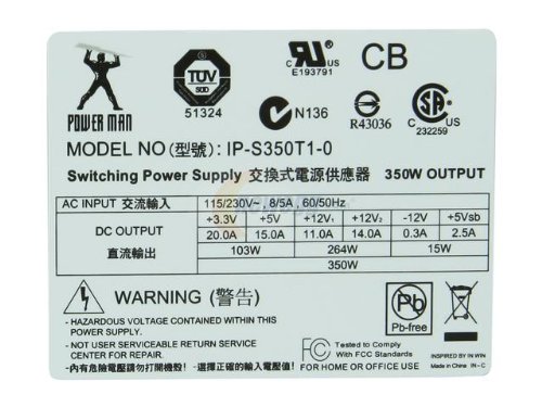
Also thanks Spellman for clarifying the wiring setup. One last question though on the ATX supply:

51DIs8QnmOL.jpg


With this supply having 2 +12V rails, one at at 11A, and the other 14A, if I were to wire all the yellow(12V) wires together would it then be at 25A, therefor being at the stall point for the motor?

And again big thanks to you guys for doing the leg work for the rest of us who aren't as inclined or brave enough to trial and error it ourselves.

the stall point is how many amps the stalled (rock stuck in mill for example) motor would draw if i understand it correctly.
 
the stall point is how many amps the stalled (rock stuck in mill for example) motor would draw if i understand it correctly.

Yeah that seems like it would make logical sense.

Also found the answer to my question, from what I found reading up on the subject online it seems that one shouldn't combine power sources of differing amperages. Guess I'll just have to look around more for a single rail ATX supply.
 
I pulled a couple motors off an old treadmill the other day, anyone here ever re-purposed a treadmill motor and will it work for this?
 
Re-reading the thread, I believe someone already thought of that, and the issue was that the motor draws 240V, rather than the household standard 120V.
 
adamranders, is this a supply that already have? If not, yes I would maybe look around for a different one. If you do have it, I would try just the yellow that connects to the motherboard, it is most likely the 14a rail. You could do a test with some grain and see if it works or not. Those psu usually have a little headroom above stated amps, if you draw too much the overload protection should kick in and shut the supply off.

edit: where is my head, probably the cpu power for the 14a
 
Re-reading the thread, I believe someone already thought of that, and the issue was that the motor draws 240V, rather than the household standard 120V.

This treadmill was indeed running on 120v.
 
adamranders, is this a supply that already have? If not, yes I would maybe look around for a different one. If you do have it, I would try just the yellow that connects to the motherboard, it is most likely the 14a rail. You could do a test with some grain and see if it works or not. Those psu usually have a little headroom above stated amps, if you draw too much the overload protection should kick in and shut the supply off.

No the picture is of one from amazon with nearly the same specs (the 12V rail specs are the same) as one a friend has laying around that I could get for free. I'll probably look around at cheapo used places like goodwill for a single rail model, but pick that one up as well to test.
 
I was just going to say something about goodwill. They also accept old computer equipment that goes to recycling, so even if they don't have something on the floor to buy, you may ask them if they have anything in the back room where they take in items.

Or, if you are like me and impatient for $19 you could get one of these: http://www.newegg.com/Product/Product.aspx?Item=N82E16817822007
It has a switch on it that you could use to turn it on/off, but you would probably still need to tie a green and black together to make it work. It will give you 20a, which has a bit more umph than my 16a.
 
So I went ahead and got the DC motor on order as well and the couplers. I have an ATX power supply that a friend had laying around. It has 2 legs rated at +12v... one says output 19A and the other -12 .8A... there are like seven different yellow wires. And almost as many if not more black. Am I supposed to tie all the yellow together or just certain ones. Also how do I know which black one to tie to the green...
 
So I went ahead and got the DC motor on order as well and the couplers. I have an ATX power supply that a friend had laying around. It has 2 legs rated at +12v... one says output 19A and the other -12 .8A... there are like seven different yellow wires. And almost as many if not more black. Am I supposed to tie all the yellow together or just certain ones. Also how do I know which black one to tie to the green...

spellman and hanna seem to be a lot better at this than me but my understanding is that all of the yellow wires are 12 volts and all of the black are ground. the green can go to any black and all of the yellow can be soldered together. the black wires can also be soldered together. run a lead from the black bundle and the yellow bundle to the motor.
i just got my power supply in the mail, went through the wires with my multimeter and the voltage values were the same as shown in the chart below.

16300625_Tc7VdP
[/url][/IMG]
 
i'm still waiting for the motor to arrive but i got to work on the power supply as soon as it got here today. i never noticed that the postal service is delivering packages on sunday, trying to stay alive i guess. anyway, this is what mine looks like so far: yellow is 12 volt, black = ground and green is wired into a black to keep it on. the other wires i'll probably cut off once i determine for sure i don't need them.

16300625_Tc7VdP
[/url][/IMG]

i'm not sure if i'll just solder the wires or find some other way to do it.
 
Motor and powersupply coming thanks for the great ideas.
 
So I received all the parts just need to build a cabinet to mount everything on. Getting the power supply setup and am wondering if anyone who has finished theirs could post a pic of how they wired to the motor,I can't seem to fit two wire connectors on the two terminal spades without them touching each other.
 
One last thing, are all the ground leads necessary or would one per 12v lead be good, my supply has more than double the grounds than 12v leads.
 

Latest posts

Back
Top