I think the esp variant powers the probes with 3v3? I wonder if there’s just not a big voltage drop somewhere?
You are using an out of date browser. It may not display this or other websites correctly.
You should upgrade or use an alternative browser.
You should upgrade or use an alternative browser.
Native ESP8266 BrewPi Firmware - WiFi BrewPi, no Arduino needed!
- Thread starter Thorrak
- Start date

Help Support Homebrew Talk - Beer, Wine, Mead, & Cider Brewing Discussion Forum:
This site may earn a commission from merchant affiliate
links, including eBay, Amazon, and others.
Unfortunatelly i have to ask additional question. I have everything soldered, connected, BUT... when I do have only one temp sensor (DS18B20) - it is working (checked all one by one), but when i have two or more connected parallelly, none is visible. I have checked all connections, I have checked all - one by one, and I have checked all only by adding/removing/changing data line (to eliminate voltage/power source issue) - as long, as only one is on data line - it works, when there is another one, it stops. How to troubleshoot it?
How long is the wiring run to your temp sensors? That is really strange, as it sounds like you’ve basically eliminated anything other than it being some kind of signal issue on the data line.
Is this the missing One-Wire pull-up syndrome?
Cheers!
Cheers!
I have 4.7k resistor. I will try with 10k and 1k - if that might help.
Going to 10k definitely wouldn’t help I don’t think.
How are you connecting everything to your controller? Are you using the RJ11/RJ45 temp breakout boards or are you doing something else?
I’m still thinking it’s most likely either some kind of noise between the D1 and the temp sensors themselves (cabling, etc) or its the batch of temp sensors.

I have 4.7k resistor. I will try with 10k and 1k - if that might help.
Some use 3k3, but you should be just fine with the 4k7 in your scenario. Using 1k may be sinking more current than is helpful in terms of reliability.
I am assuming you have things working with either single temp probe. Sometimes the leads are mislabelled if you bought pre-built sensors, always worth double checking.
Unsure how you are joining up the sensors, but an issue I sometimes see is that the DC negative and GND as used in AC circuits are assumed to be the same thing by control panel builders. This will take out your temp sensors, and can easily happen inadvertently, as some connectors (like some XLR connectors), bridge the typical ground pin for that connection type with like the plug jacket and receptacle. This is an issue that often doesn't exist when builders are bread-boarding or prototyping, but comes up when they actually install in a panel.
Lalo_uy
Well-Known Member
May be the pullup is no t ok. use a 3k3 ohms pull up for stronger current
What platform is being used here - Uno or ESP? If the former, the sensor(s) VCC should be connected to 5V and the pull-up should go to 5V as well. Otoh, on the ESP the VCC should go to 5V and the pull-up should go to 3.3V. These are optimal configurations for each.
As to the value, I run five 3-meter long probes on a pair of Raspberry Pi's with 4.7K pull-ups to 3.3V. And all of my BrewPi minions run three 3-meter long probes with 4.7K pull-ups to 5V.
I can't see a problematic configuration getting better with a higher numeric value pull-up, and I'd wonder why it might take a lower numerical value to work...
Cheers!
carrsgarage
Well-Known Member
- Joined
- Apr 19, 2018
- Messages
- 98
- Reaction score
- 11
I had my sensors connected to 5V and noticed that the temperature kept creeping up. I touch he'd the sensors and they were getting HOT. I moved them over to 3.3V and everything straightened out. Weird.
Bigdaddyale
Well-Known Member
Saw something like that a while back. It's a nice concept and I like a lot of what he's done there. I think the challenge we have with our various Pi-based solutions is that they do not lend themselves well to something like this. For instance, Fermentrack is running a database and they tend to not like people playing with their storage.
The better solution for long-term Pi health is to use an SSD. With the B+ it's as easy as flashing the image to the new drive and plugging it in.
I fragged TWO of my SD cards this past weekend. No excuse since I have an SSD sitting right next to me.
I should also point out that you can use just about ANY storage. Here's one of my mules with a regular-old 256G USB drive as a boot drive:
Code:
Filesystem      Size  Used Avail Use% Mounted on
/dev/root       230G  4.7G  216G   3% /
devtmpfs        460M     0  460M   0% /dev
tmpfs           464M     0  464M   0% /dev/shm
tmpfs           464M   13M  452M   3% /run
tmpfs           5.0M  4.0K  5.0M   1% /run/lock
tmpfs           464M     0  464M   0% /sys/fs/cgroup
/dev/sda1        44M   22M   22M  51% /boot
tmpfs            93M     0   93M   0% /run/user/1000
Last edited:
- Joined
- Apr 16, 2013
- Messages
- 9
- Reaction score
- 1
I recently connected an iSpindel that I assembled to Fermentrack. I haven't calibrated the gravity sensor yet but the temperature reported and plotted in Fermentrack is about 170 F. The temperature shown in the log is correct, closer to a room temp of 75 F. Any ideas why the temp is misreported in Fermentrack?
Log -------
'{"name":"iSpindel123","ID":13064362,"token":"fermentrack","angle":44.68406,"temperature":75.08749,"temp_units":"F","battery":4.202294,"gravity":10.21605,"interval":30,"RSSI":-57}'
Log -------
'{"name":"iSpindel123","ID":13064362,"token":"fermentrack","angle":44.68406,"temperature":75.08749,"temp_units":"F","battery":4.202294,"gravity":10.21605,"interval":30,"RSSI":-57}'
I’m guessing a C to F issue. 75 C is about 168 F so maybe you have a setting off? (Not messed with this, just guessing).
I recently connected an iSpindel that I assembled to Fermentrack. I haven't calibrated the gravity sensor yet but the temperature reported and plotted in Fermentrack is about 170 F. The temperature shown in the log is correct, closer to a room temp of 75 F. Any ideas why the temp is misreported in Fermentrack?
Log -------
'{"name":"iSpindel123","ID":13064362,"token":"fermentrack","angle":44.68406,"temperature":75.08749,"temp_units":"F","battery":4.202294,"gravity":10.21605,"interval":30,"RSSI":-57}'
I’m guessing a C to F issue. 75 C is about 168 F so maybe you have a setting off? (Not messed with this, just guessing).
Temp format wasn’t initially sent with the iSpindel data, so Fermentrack always assumed C. I thought I had code to check that when it was added, but it must not be working. I’ll take a look.
- Joined
- Apr 16, 2013
- Messages
- 9
- Reaction score
- 1
Temp format wasn’t initially sent with the iSpindel data, so Fermentrack always assumed C. I thought I had code to check that when it was added, but it must not be working. I’ll take a look.
Thanks,
I do have the spindel configured in degrees F. So it makes sense that it's a conversion issue.
- Joined
- Apr 16, 2013
- Messages
- 9
- Reaction score
- 1
I'll try to get the bug in Fermentrack fixed regardless. Glad you have a fix in the interim, though!@LBussy and Thorrak,
Thanks for pointing me in the right direction. Setting the iSpindel to output in deg C fixed this temperature issue.
carrsgarage
Well-Known Member
- Joined
- Apr 19, 2018
- Messages
- 98
- Reaction score
- 11
A funny thing happened to my ESP8266 controller last night:
I started fermenting a beer Sunday using Fermentrack for the first time. Everything was going well until last night. I added a small fan to the chamber around dinner time since I figured it would help things even out inside the chamber. I checked it a couple of times before bed and it was still heating and cooling. This morning I checked it and it wasn't communicating. Upon further investigation, I found that the 10A fuse inline with the 5V power supply and the heating and cooling outlets had blown.
Any idea what might have happened? The fan (which is plugged into the same outlet as the ESP8266 but has its own power supply) was still running. I can't help thinking the addition of the fan indirectly caused the fuse to blow, perhaps by confusing the heating/cooling predictions.
Not gonna say that the fan had nothing to do with it, because it's at least a coincidence, but I can't think of any way the PID loop would have changed so dramatically so as to blow a fuse. There's minimum run and off times which would have prevented that.
Is the 10A fuse in one of those fuse/lighted socket/switch combo packages? If so, I recall someone posting somewhere that they aren’t really capable of handling anything close to that amount of current for any amount of time. I don’t recall exactly why, though.
carrsgarage
Well-Known Member
- Joined
- Apr 19, 2018
- Messages
- 98
- Reaction score
- 11
Is the 10A fuse in one of those fuse/lighted socket/switch combo packages? If so, I recall someone posting somewhere that they aren’t really capable of handling anything close to that amount of current for any amount of time. I don’t recall exactly why, though.
That's exactly what it is!
I'm using a fermwrap for the heat in a Haier wine fridge. I wouldn't think any of this would come close to blowing the fuse. It lasted 4 days, at least....
Bigdaddyale
Well-Known Member
It was day_tripper who posted the warning but I can't find the post.Is the 10A fuse in one of those fuse/lighted socket/switch combo packages? If so, I recall someone posting somewhere that they aren’t really capable of handling anything close to that amount of current for any amount of time. I don’t recall exactly why, though.
I am that someone
If you remove the switch module from the bulkhead it'll have the actual rating molded into the shell. My "10A" bulkheads had 6A switches and eventually they would burn through one set of points and then the other. I ended up bypassing the switches on all of those bulkheads (four minions worth) so now it's a cord-pull shut-off...
Cheers!
[edit] I should note that I've never had the supplied 10A mini-fuses blow on any of these AC bulkheads. Just the switch module failures. On one of those one of the terminals actually fell off the module when I popped it out of the bulkhead, so they're clearing overheating and failing...
Last edited:
What's the model on the fridge?
Generally, if you are using a fuse like that on a motor (the fridge compressor is a motor) you want a slow-blow. When a compressor starts up the load can be many times higher (we used to allow for a surge of 5-6 times the running amperage) for a brief time. It's possible the compressor on the fridge has a rating label. If so, look for something that says "LRA" (Locked Rotor Amps). A fridge that has a rating of 1.1 running amps like this little 1.1 cu ft model here can draw 5A when it starts up.
So ... look for a label and/or take an ammeter to the compressor when it's running. That may give you a clue. Get a slow-blow fuse to replace the one you have on there. See what that does for you.
Hey @Thorrak
I have an idea for an enhancement;
I typically use this just for temperature monitoring, i'm not in a position to start controlling things yet.
Sometimes my fermenter is in an inconvenient place and running wires too it causes traffic issues in my house. I've tried powering it from a USB power pack and it doesn't last very long.
I thought it might be useful as an enhancement to use the deep sleep mode on the ESP and power off the LCD LED to save power.
I would pull it from github and do it myself but the amount of code in this project is mind boggling and honsetly don't know how you manage all this yourself. I think it would correlate a bit with your reconnect from power loss enhancement.
For what its worth, I went ahead and made this.
I originally tested a Wemos D1 Pro and 1 DS18B20 and the LCD on a 15,000 mAh battery pack and it lasted about 3.5 days.
After researching this a bit, what made most sense / was easiest was to add another Wemos D1 Pro into the mix and utilize the ESP Deep sleep functionality. Now I have a Wemos D1 Pro that is on all the time, but only 'awake' for 2 minutes every 20 minutes. In the 2 minutes, it uses a TIP120 to keep the original BrewPi Wemos D1 on, take a few readings and then it gets powered off when the first Wemos D1 goes to sleep. It works great!
Testing Setup
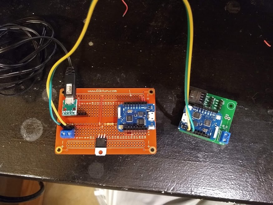
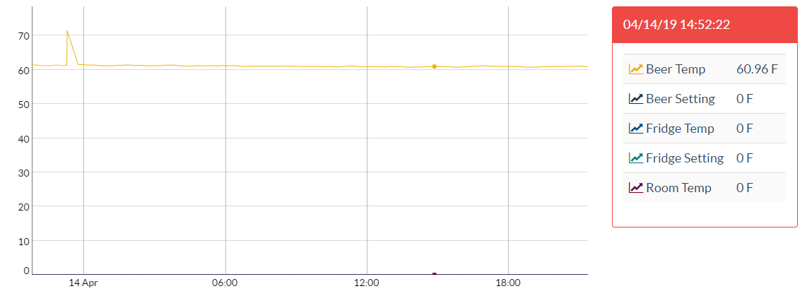
Even for a short plot that's surprisingly clean under the circumstances.
But while that may work for monitoring it might not work so well for control, it depends on how the PID logic utilizes volatile memory...
Cheers!
But while that may work for monitoring it might not work so well for control, it depends on how the PID logic utilizes volatile memory...
Cheers!
JnR_NaT
Active Member
- Joined
- Feb 17, 2019
- Messages
- 40
- Reaction score
- 10
A few quick questions for the brains trust
1. Is the jumper in the correct position for the 2 relay board?
2. Does IN1 relate to K1 on the relay board?
3. What is up with this RJ-11 PCB holes, I can not find and RJ-11 PCB socket that has the same hole pattern?
Thanks in advance
**Edit**
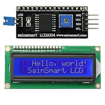
I got the relay working all good now, however when I plug the LCD in, all I get is the squares and no text. I have a 20x4 I2C screen
1. Is the jumper in the correct position for the 2 relay board?
2. Does IN1 relate to K1 on the relay board?
3. What is up with this RJ-11 PCB holes, I can not find and RJ-11 PCB socket that has the same hole pattern?
Thanks in advance
**Edit**
I got the relay working all good now, however when I plug the LCD in, all I get is the squares and no text. I have a 20x4 I2C screen
Attachments


Last edited:
A few quick questions for the brains trust
3. What is up with this RJ-11 PCB holes, I can not find and RJ-11 PCB socket that has the same hole pattern?
I think you made the same mistake, that I made when ordering my RJ45 Jacks. As I was told, “It’s because that jack is designed to have the cable inverted when it’s plugged in.”
The incorrect one is on the left, the correct one is on the right. Notice how the contact pins are on the same side as the pins that solder to the PCB?...you don’t want that. [emoji37]


A few quick questions for the brains trust
I got the relay working all good now, however when I plug the LCD in, all I get is the squares and no text. I have a 20x4 I2C screen
I can’t speak on your LCD Module, but on mine I had something that looked like a blue terminal block with a screw adjuster in it. I used a screwdriver and adjusted my contrast to fix the same issue that you currently have.
Yes.1. Is the jumper in the correct position for the 2 relay board?
IN1 and IN2 are the two relays, yes.2. Does IN1 relate to K1 on the relay board?
Possibilities:I got the relay working all good now, however when I plug the LCD in, all I get is the squares and no text. I have a 20x4 I2C screen
- You might have the wires backwards. Make sure pin 1 is on pin 1 of the relay. If you have the boards oriented so that the USB connection towards you on the Arduino and the LCD screen facing you with the pins oriented to the top, the ribbon should be straight - left most pin on the board is left-most on the LCD.
- Check the adjustable resistor. There's a very narrow range where the LCD displays correctly - most people are surprised how far they need to turn it.
Bigdaddyale
Well-Known Member
Yes, turn the screw about 20 revs each way.I can’t speak on your LCD Module, but on mine I had something that looked like a blue terminal block with a screw adjuster in it. I used a screwdriver and adjusted my contrast to fix the same issue that you currently have.
I am trying to install Brewpi on my Raspberry pi and when I run
sudo ./install.sh I get an error..
Package libapache2-mod-php5 is not available.....
some more errors on the end are...
E: Package 'php5' has no installation candidate....
I running the new version of raspbian Stretch
I gave up on installing Fermentrack as I could not get the firmware to flash
Jerrydfl
Bigdaddyale
Well-Known Member
https://www.brewpiremix.com/I am trying to install Brewpi on my Raspberry pi and when I run
sudo ./install.sh I get an error..
Package libapache2-mod-php5 is not available.....
some more errors on the end are...
E: Package 'php5' has no installation candidate....
I running the new version of raspbian Stretch
I gave up on installing Fermentrack as I could not get the firmware to flash
Jerrydfl
http://www.fermentrack.com/
Bigdaddyale
Well-Known Member
To run old school Brewpi with Strech is a pia- LBussy made it easy with his new Remix program. RPI and UNO R 3
Thorrak created the newer improved version of BrewPi with Fermentrack. RPI and ESP8266 D1 mini
Pocketman created BrewPi Less which runs on an ESP8266 D1 mini
Thorrak created the newer improved version of BrewPi with Fermentrack. RPI and ESP8266 D1 mini
Pocketman created BrewPi Less which runs on an ESP8266 D1 mini
For the most part, "old school" BrewPi is discussed in this thread: https://www.homebrewtalk.com/forum/...wpi-fermentation-controller-for-cheap.466106/I am trying to install Brewpi on my Raspberry pi and when I run
sudo ./install.sh I get an error..
Package libapache2-mod-php5 is not available.....
some more errors on the end are...
E: Package 'php5' has no installation candidate....
I running the new version of raspbian Stretch
The command you want is this (all one line):
curl -L install.brewpiremix.com | sudo bash
If you have issues with it, drop in that other thread and we'll help you out.
JnR_NaT
Active Member
- Joined
- Feb 17, 2019
- Messages
- 40
- Reaction score
- 10
Yes.
Er ... um ... or is this an I2C? I think it is ... So ignore #1. Possible that you have older firmware? it should auto-detect. There is a contract trimmer on that one too so try that. Also make sure SDA and SLC are wired properly and not reversed.
- Check the adjustable resistor. There's a very narrow range where the LCD displays correctly - most people are surprised how far they need to turn it.
Yes, turn the screw about 20 revs each way.
I don't have an adjustable resistor.
I swapped the SCA and SCL but there was no difference. Is there a way to update the firmware of the LCD
Bigdaddyale
Well-Known Member
The blue square on the back of the displayI don't have an adjustable resistor.
I swapped the SCA and SCL but there was no difference. Is there a way to update the firmware of the LCD
Similar threads
- Replies
- 3
- Views
- 1K
- Replies
- 9
- Views
- 2K

Latest posts
-

-
-

-
-

-
 Illinois 14 gallon stainless conical
- Latest: OakIslandBrewery
-
