MM2 Mill powered with Garage Door Opener?

Homebrew Talk - Beer, Wine, Mead, & Cider Brewing Discussion Forum

Help Support Homebrew Talk - Beer, Wine, Mead, & Cider Brewing Discussion Forum:

This site may earn a commission from merchant affiliate links, including eBay, Amazon, and others.
No ideas, without seeing the "business end".
Is that a "screw drive" opener?

If so, it may limit your options, as it only has to spin the screw, to lift the door.

What is the actual "drive"..........Belt driven?
 
No ideas, without seeing the "business end".
Is that a "screw drive" opener?

If so, it may limit your options, as it only has to spin the screw, to lift the door.

What is the actual "drive"..........Belt driven?


The screw is the drive. It's a direct drive, no belts or gears that I can see.


Sent from my iPad using Home Brew
 
How would it go any faster than any other door opener motor. Just has more torque and is smoother are the claims when used in its original manor


Sent from my iPad using Home Brew
 
Yes the screw is worthless. But it's a direct drive to the mill with lovejoy couplers and the way I look at it, that's a good thing.


Sent from my iPad using Home Brew
 
Why ask questions if you don't want to hear the answers?

The screw drive *is* the gear reduction in the screw-type garage door opener. Without the screw drive, the motor will both spin the mill to fast and not have enough torque.
 
When did I not like the answers? I have yet to even power the unit up, so I am curious if anyone here has used one. If it doesn't work, I am out zero dollars. I also have a large/heavy 1750rpm 1/2hp motor I could use, but sheaves have went up too much in price for me to justify at this point.
 
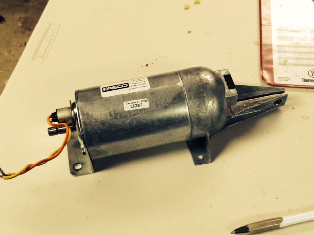
30Bones - I have a Genie screw drive motor I'm currently working with. I don't know the RPM, but I know it is way too fast to run my MM2. You will still need a way to reduce speed / increase torque with a screw drive motor. In the intended application, the screw itself performs the task.

In chain drive motors (and presumably belt drives too), there is typically a plastic worm gear that drives a circular ("normal") gear attached to the shaft of the chain sprocket. See http://www.surpluscenter.com/110-RP...EARMOTOR/edp_no=38131/shop.axd/ProductDetails. The white gear meshes with the worm gear, cased in black coming directly off the motor. The white gear is on the same shaft that spins the chain sprocket.

In screw drive openers, this worm gear is the equivalent of the ~8ft screw.
 
Awesome! That motor was not available that I could find when clicking on the older links in this thread.
 
Yup, I'm still here, and I too wish i would have picked up one from surplus center when I started this thread. But I'm making slow progress with the screw drive I found in the dumpster, first having to reverse engineer the drive board since the control board was shot (shorted parts and burnt traces).
 
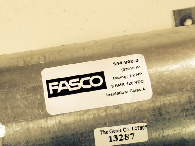
Great thread! I'm trying to adapt a garage door motor also, but am running into a different problem than most here. The motor I have is 1/2 hp out of a Genie unit but it is a DC motor. Anybody got some ideas how to build a inverter on the cheap to make this work?

Cheers! :mug:

Motor_1.JPG


Motor_2.JPG
 
That looks strangely like mine (see attached, different sticker though). I'm using the original control board for the inverter (the one that the motor plugs into, not the one on the bottom of the opener). Do you still have it around? If so, I can post the reverse engineered schematic.

How were you planning on attaching this to the mill? My plan was to modify the first screw to run the pulley/sheave.

20140702_193912.jpg

20140702_192333.jpg
 
I do still have the board but couldn't figure out how to get it into the loop. As far as a connection is concerned I figured on trying to locate a 3/8" shaft spider coupling (jaw coupling).

Whatever you have that you'd care to share on this would be appreciated.

Cheers!
 
Great thread! I'm trying to adapt a garage door motor also, but am running into a different problem than most here. The motor I have is 1/2 hp out of a Genie unit but it is a DC motor. Anybody got some ideas how to build a inverter on the cheap to make this work?

Cheers! :mug:

You actually need a converter (AC -> DC). You could isolate the mains with a transformer then us a bridge rectifier circuit....120VDC is still deadly though so isolating the mains probably isn't necessary.

In any case, be careful
 
You actually need a converter (AC -> DC).

Yup. I should have caught that being an electrical engineer. inverters are DC -> AC.

On the main power board, there is a transformer for the low voltage side, but the section that powers the motor is all referenced to the mains. I'll dig up the schematic tonight, make sure it is intelligible, and post it here.

Thanks. As a long-time-ago teletype repairman for the Army my electrical knowledge is way short of yours. But I can read a schematic (usually). We used to have full-wave bridge rectifiers in power supplies but I doubt they even use them any more.

I appreciate your input on this.

Cheers!
 
12V Battery charger won't do it.

120VAC full wave rectified and averaged is ~108VDC. In other words, don't stick your fingers where they shouldn't be!

Not that you can see it in the picture, but there is a full-wave bridge rectifier (GBJ series available at Digikey, don't know the exact part number off the top of my head) attached to a slab of aluminum at the bottom, right next to the motor mount.
 
Not that you can see it in the picture, but there is a full-wave bridge rectifier (GBJ series available at Digikey, don't know the exact part number off the top of my head) attached to a slab of aluminum at the bottom, right next to the motor mount.

This is where the time lapse is showing up. The full-wave bridge rectifiers we used in the early 1970's looked like several square slabs separated by insulators - the whole affair was probably 5" square and 2" thick. They stunk like heck when they burned out, too! (Don't ask how I learned this.) Haven't worked with this stuff in years and the new components look completely different. The good news is that the electricity itself still runs just like it did back then. :)

Just for what it's worth, do you think the voltage drop to 108v is of any concern to the longevity of the motor? Or, as pointed out earlier, since the 115v house current is a nominal voltage, should I be more concerned with voltage spikes and therefore need some sort of filter in the circuit to keep those under control?
 
The motor i'm sure is designed for ~108VDC, so longevity is not of concern. If you are going to reuse the power board, you shouldn't have to worry about power spikes or filtering, as you would be reusing the manufacturer's original parts, the only difference being what the motor is driving.

The standard wall outlet (in the US anyway) is 115-120VAC or Vrms. Wikipedia has an explanation and the equations to get VDC from Vrms - http://en.wikipedia.org/wiki/Rectifier#Full-wave_rectification.
 
Any new word on where to get the motor. Looks like the surplus website is out and the two door businesses I called said no. There's a few more I can try though. Wanted to try this before I go buy the $50 drill but about to just spend the money.
 
Sorry it took so long to get the schematic uploaded. Life got in the way and I had not finished interpreting my notes to convert to a schematic.

Genie Garage Door Schematic
*Note: As I reverse engineered this, there may be errors. Use at your own risk.

Tomorrow I hope to find out how fast the motor actually spins with no load.
 
Yikes! This motor spins far faster than I thought. Unloaded, I get ~1.15kHz on the 12 toothed speed sensor, which is 93Hz shaft speed, or 5750-6000 RPM. So the gear ratio would have to be 1:38 to get down to the ideal 150RPM monster mill recommends.

As a double check, the screw drive is approx. 8 threads per inch, and the door travel is about 8 ft. This would be 768 revolutions to open the door, and at 6000RPM gives about 7.5 seconds to open. My chain drive takes about 10 seconds and if memory serves from my research before purchasing my last opener, screw drives are a little faster.

In retrospect, I should have spent a few minutes doing math before working on getting this motor running... :(

Edit: Corrected ratio and RPM for the monster mill.
 
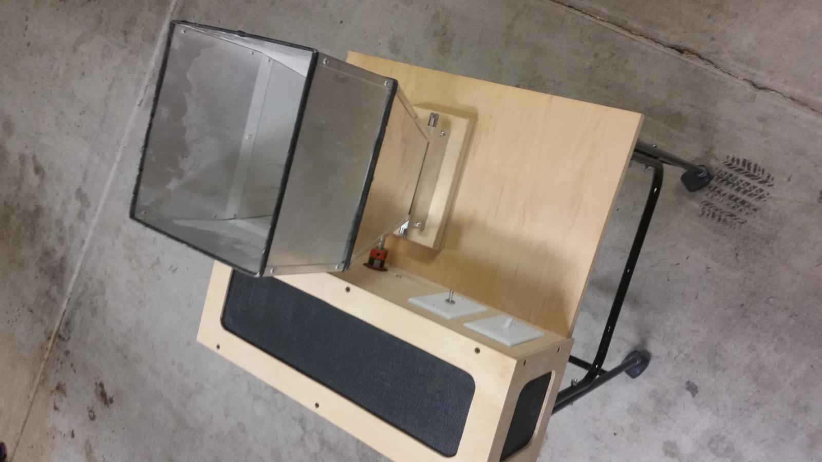
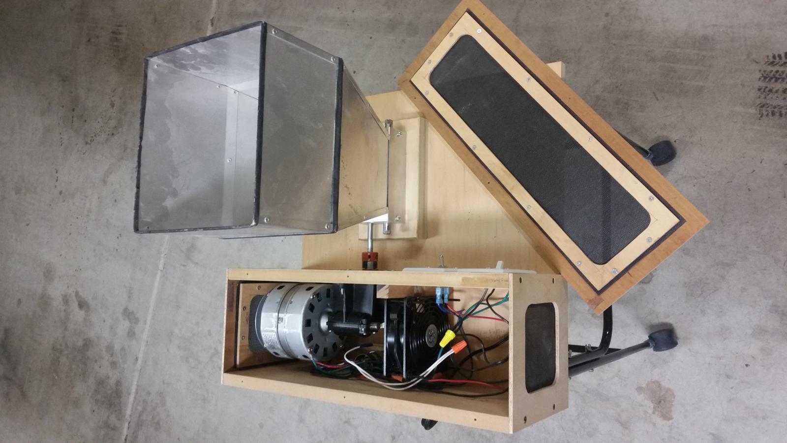
Well it's been almost 2 years since I bought the motor, Lovejoy couplings and toggle switch. I finally got around to motorizing my Barley Crusher. The rolling stand is from a bird cage I almost threw away last week. The other materials came from scrap pieces I've had around for 14 years. Thanks again for the write up Wilconrad.

Motorized Grain Mill 1.jpg


Motorized Grain Mill 2.jpg
 
Awesome, nice looking build TripleHopped! You'll be glad to hear that my mill is still cranking away with this setup, haven't had any issues. Happy milling!
 
Back
Top