Thank you to everyone for the contributions and especially to P-J for all of the diagrams. I've browsed the entire thread, posted my own, and cannot seem to get over my mental block of how to plan my system to get what I want, so, I thought this would be a good place to go.
I apologize in advance for the long winded post.
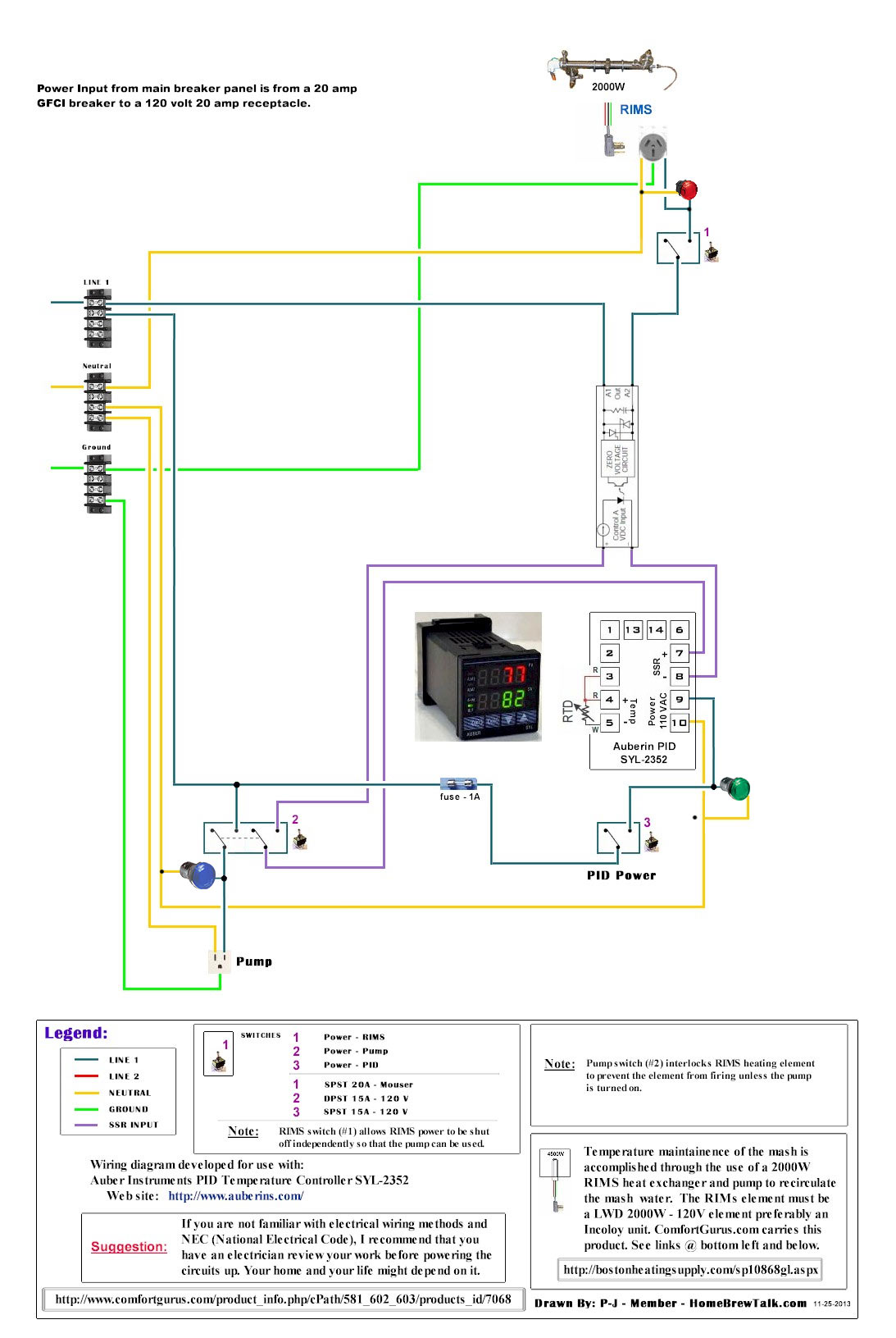
I want a 3-vessel, e-HERMS, with two pumps. One 5500watt element in HLT, one 5500watt element in the BK. I'd like one
Auber PID to control the HLT and one
Auber Boil Controller for the BK. I will have the option to use 40amp service that is currently unused in the breaker box or 50amp service after we change from an electric range to a gas range. I'd like an E-stop, a Keyed power on switch, toggle switches to give power to elements and pumps with indicator lights for elements and pumps. I've seen a number of schematics, compared them to each other and with Kal's site. I am still a bit lost.
Could I bring the service wires in to a NC E-stop, to the NO Key Power switch, to the distribution blocks, then to the contactors, parts, and lights? Or do I need a contactor before getting to the distribution blocks? Should I put the E-Stop before the distribution blocks? Should I put the Key switch before the distribution blocks? Other than that, I believe I would need 2 contactors and 2 SSRs and the various switches and lights. Is there anything else?

") . I am checking out some builds and I see terminal bus strips, I think? I'd need 4 of those at the start of the wiring; GND, Neutral, Line 1 and Line 2, correct? I'm confused though on this:
. I am checking out some builds and I see terminal bus strips, I think? I'd need 4 of those at the start of the wiring; GND, Neutral, Line 1 and Line 2, correct? I'm confused though on this: