You are using an out of date browser. It may not display this or other websites correctly.
You should upgrade or use an alternative browser.
You should upgrade or use an alternative browser.
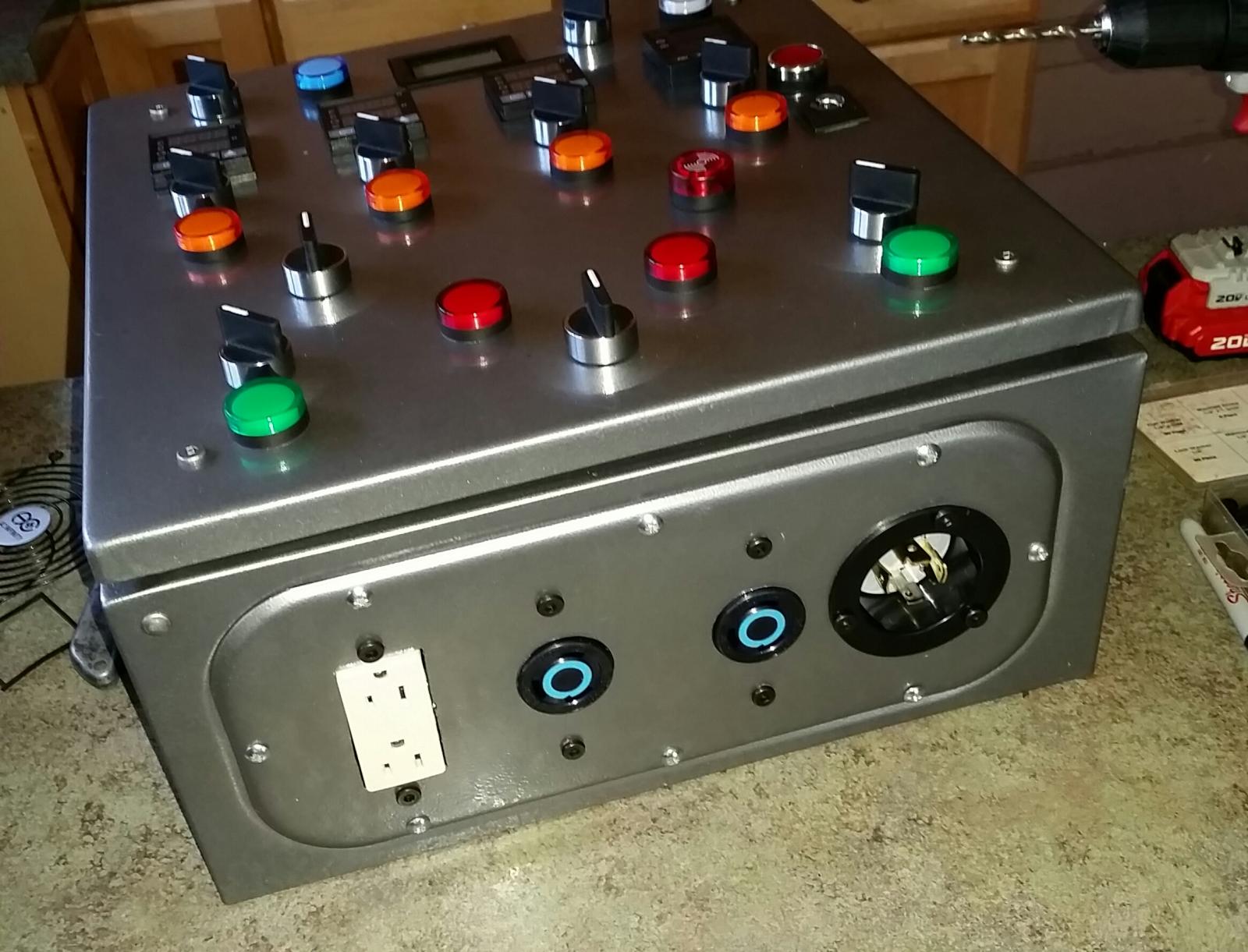
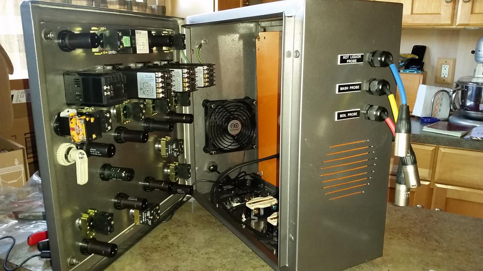
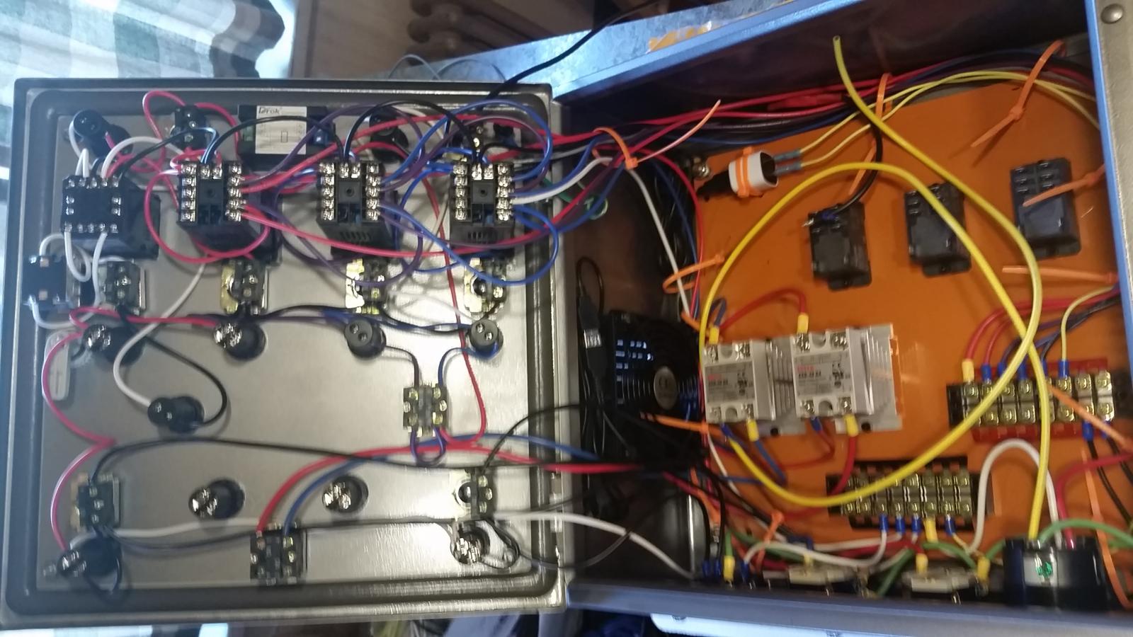
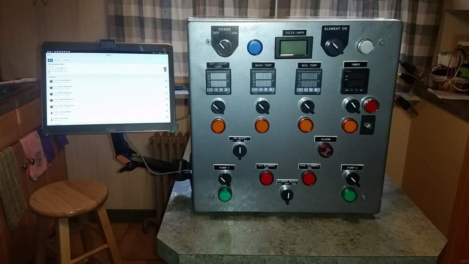
Huge E-HERMS build, 3 keggles, control panel, stir plate, ferm controller, 61 pics
- Thread starter azwillnj
- Start date

Help Support Homebrew Talk - Beer, Wine, Mead, & Cider Brewing Discussion Forum:
This site may earn a commission from merchant affiliate
links, including eBay, Amazon, and others.
azwillnj
Well-Known Member
Can you post a wire schematic of the control box. And what are the dimension of the control box
I don't have one yet, sorry. I have been working on it in my free time, but with work and all the other projects I am working on there's not much free time. I will need to create a schematic in the near future as I have been tasked with converting this system to a 1bbl and building it for a pilot system for my local micro brewery. So stay tuned, I should have something soon-ish.
CraSYDiamond
Member
Any luck with the wiring diagram yet? Do you have a detailed shopping list for the whole build?
Smellyglove
Well-Known Member
- Joined
- May 17, 2013
- Messages
- 2,807
- Reaction score
- 807
Where's my sunglasses? 
But. I don't get it with un-insulated hoses. Don't you lose temp?
But. I don't get it with un-insulated hoses. Don't you lose temp?
sandyeggoxj
Well-Known Member
How did you wire in the volt/amp meter? I like that little meter. I have noticed major swings in voltage in my power supply depending on the day. When I start heating my strike water I usually probe my power input with a multimeter. This would be much easier.
L
lpgasbob
Guest
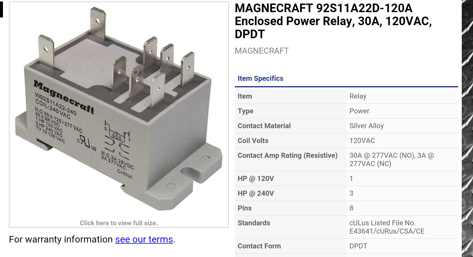
Hello what type of relays did you use
KartRacer54
Well-Known Member
Responding to markthisthread. Incredible build! You are simply amazing with the detail.
MedicMang, his whirlpool arm is made of Loc-Line. You can Google "loc-line" and "brewing" for tons of hits to learn more. I use it myself in my system, and love it.
This is one of the best if not the best documentations of an electric setup I have seen. My setup is stone age by comparison. Well done. Thanks for taking the time to document and share. If I ever go three vessel this will be what I will try to emulate.
Unrelated to the build. How did you put so many pictures in one post. I thought the limit is 10? Just curious.
iijakii
Well-Known Member
Do you have the little plastic mypin supporters always falling off? I can't get mine to lock up. Been thinking about tapping them to the sides of the PID...
azwillnj
Well-Known Member
Wow, I suck at replying. Sorry everyone.. here goes:
Maybe, but I don't care, there's no part in the process where hot liquid is running through the tubes without the elements firing.. or without me wanting it to cool down. Even when boiling wort is running through the lines I can grab the tubes with my bare hands. The cam locks will burn the **** out of you though, haha.
I wired it directly across the Hot A and Hot B lines, and I took the Amperage off the Hot A line. In my old house there was a massive swing in the voltage, I called the power company and they replaced a transformer that was going bad.. maybe call your power company?
Here's where I got the original set:
http://www.brewhardware.com/product_p/mashrecirculation.htm
I noticed it was digging a hole in the grain bed so I bought this and put it on the end. I had to drill out the holes a little but it's an awesome upgrade:
http://www.amazon.com/dp/B00065UDB0/?tag=skimlinks_replacement-20
SSR's for the PID Controllers and cheap DPDT mechanical relays from ebay for the main power.
I hosted on imgur and linked to them.
They were constantly releasing, I got pissed and put a drop of superglue on each one. I figured if I was removing it down the line it was gonna be because it failed and I didn't care about breaking it.
Also, thanks everyone for the praise, it was a lot of work, and a lot of money but absolutely worth it. I currently have fermenting a Lost Abbey Angel's Share Clone that had an OG of 0.123, I am shooting for 15.1% abv with WLP099.. Crossing my fingers.
Where's my sunglasses?
But. I don't get it with un-insulated hoses. Don't you lose temp?
Maybe, but I don't care, there's no part in the process where hot liquid is running through the tubes without the elements firing.. or without me wanting it to cool down. Even when boiling wort is running through the lines I can grab the tubes with my bare hands. The cam locks will burn the **** out of you though, haha.
How did you wire in the volt/amp meter? I like that little meter. I have noticed major swings in voltage in my power supply depending on the day. When I start heating my strike water I usually probe my power input with a multimeter. This would be much easier.
I wired it directly across the Hot A and Hot B lines, and I took the Amperage off the Hot A line. In my old house there was a massive swing in the voltage, I called the power company and they replaced a transformer that was going bad.. maybe call your power company?
I hate to ask such a stupid question but where did you get the sweet whirlpool arm?
Here's where I got the original set:
http://www.brewhardware.com/product_p/mashrecirculation.htm
I noticed it was digging a hole in the grain bed so I bought this and put it on the end. I had to drill out the holes a little but it's an awesome upgrade:
http://www.amazon.com/dp/B00065UDB0/?tag=skimlinks_replacement-20
Hello what type of relays did you use
SSR's for the PID Controllers and cheap DPDT mechanical relays from ebay for the main power.
Unrelated to the build. How did you put so many pictures in one post. I thought the limit is 10? Just curious.
I hosted on imgur and linked to them.
Do you have the little plastic mypin supporters always falling off? I can't get mine to lock up. Been thinking about tapping them to the sides of the PID...
They were constantly releasing, I got pissed and put a drop of superglue on each one. I figured if I was removing it down the line it was gonna be because it failed and I didn't care about breaking it.
Also, thanks everyone for the praise, it was a lot of work, and a lot of money but absolutely worth it. I currently have fermenting a Lost Abbey Angel's Share Clone that had an OG of 0.123, I am shooting for 15.1% abv with WLP099.. Crossing my fingers.
Last edited by a moderator:
jcc4507fly
Well-Known Member
- Joined
- Dec 27, 2012
- Messages
- 191
- Reaction score
- 17
Is there anything you would change or do different? I'm currently building an eherms, except my keggles are bottom draining. I would appreciate any words of wisdom you have to offer.
azwillnj
Well-Known Member
Is there anything you would change or do different? I'm currently building an eherms, except my keggles are bottom draining. I would appreciate any words of wisdom you have to offer.
I'm sure there are lots of them but I'll see what I can come up with off the top of my head.
- The whole ice in the HLT thing works but a plate chiller works better.
- Speaking of a plate chiller, get a filter or something for the drain on the boil kettle, or make a hop spider, those hop particles and the hot break really jam up a plate chiller.
- Go with bigger relays and higher gauge wire right off the bat, it will be easier to upgrade to either 2 elements or a higher power one in the future. (4500w is perfect for up to 10 gal batches in the kegs, just saying if you ever got a bigger kettle)
- Go with all Auber PID's they are more expensive but the auto tune is better.
- They sell power jumpers for the power block I got, it would have made it cleaner and easier to install instead of using short wires.
If I think of anything else I'll post.
Alex.
jcc4507fly
Well-Known Member
- Joined
- Dec 27, 2012
- Messages
- 191
- Reaction score
- 17
Thanks!!
Great job Alex. I like your idea of controlling the HLT element from either the HLT or MASH PID controller. I'm working on a panel design and may include this feature.
Additionally the aeration tube is an elegant way of oxygenation. Good application of Bernoulli's principle.
Thank you for the inspiration.
Additionally the aeration tube is an elegant way of oxygenation. Good application of Bernoulli's principle.
Thank you for the inspiration.
azwillnj
Well-Known Member
[About a year ago I posted this thread.
The most requested thing in this thread, and the accompanying Reddit thread was a wiring diagram.
Life got crazy, I got a new job, and never found the time to make the diagram... until now! Without further adieu may I present the long awaited wiring diagram.
Imgur link: http://imgur.com/l8fnpjM
JPG link: http://i.imgur.com/l8fnpjM.jpg
Sorry about the watermark, it took me a ton of time to make this and wanted to at least protect the idea. With that being said, I invite and encourage everyone to use this design and share this design as much as you want. Also, feel free to ask as many questions as you want.
Alex.
Wow! Nice setup. I'm considering upgrading to an EHERMs system from my current RIMS tube setup. Your gear is inspiring. I have a few questions.
1. Do you have a ballpark cost of the components? I've been researching Kal's setup but I think I like yours better.
2. Do you have a detailed parts list you could provide? Thanks a ton for for the wiring diagram!
I'm not the smartest guy in the world and any help would be welcome. I built my controller for my current setup, but my head almost exploded. Of course, I also made the controller undersized as I was only using 110v. Thanks in advance. I'm looking forward to upgrading.
wapitiscat
Well-Known Member
What type of control panel receptacles did you use for the heating elements?
Todd
Todd
azwillnj
Well-Known Member
What type of control panel receptacles did you use for the heating elements?
Todd
L6-30R and L6-30P
wapitiscat
Well-Known Member
L6-30R and L6-30P
Got it. L14 for the panel power supply and L6's for the heating elements.
Todd
I'm following your wiring diagram but seem to have hit a mental block. From the element off-on switch to the 3 way selector switch (hlt/off/mash) it shows the lights coming from the top left & right but then it shows bridging the two wires to go to the 3 way switch for the hlt/off/boil. Wouldn't this cause both the hlt & mash lights to indicate on all of the time? Unless the switch is in the off position. 
I'M following your diagram but taking your suggestions of using the same pid controllers and I've added an auber timer.
Hopefully you are still following this thread.
I'M following your diagram but taking your suggestions of using the same pid controllers and I've added an auber timer.
Hopefully you are still following this thread.
azwillnj
Well-Known Member
I'm following your wiring diagram but seem to have hit a mental block. From the element off-on switch to the 3 way selector switch (hlt/off/mash) it shows the lights coming from the top left & right but then it shows bridging the two wires to go to the 3 way switch for the hlt/off/boil. Wouldn't this cause both the hlt & mash lights to indicate on all of the time? Unless the switch is in the off position.
I'M following your diagram but taking your suggestions of using the same pid controllers and I've added an auber timer.
Hopefully you are still following this thread.
I think you're talking about the green line that goes to the bottom 2 contactor blocks on the "PID Select Switch"? If so, here is the explanation:
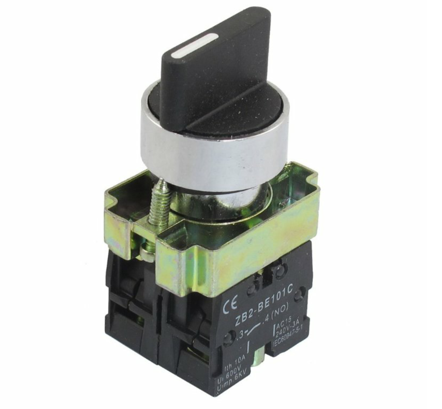
In those 3-way switches all the contactor blocks are NO (normally open).
The switch has 3 positions, when the switch is in the center all the contactor blocks are disengaged, all NO in this case.
When the switch is to the left the contactors on the left are closed completing the circuit on the HLT SSR Feed and the HLT PID LED while keeping the contactors on the right side of the switch open.
When the switch is to the right the contactors on the right side are closed completing the circuit on the Mash SSR Feed and the Mash PID LED while keeping the contactors on the left side of the switch open.
In the case of the bridged LED wire, you are supplying power to both contactors simultaneously but you are only activating one at a time because of the nature of the 3-way switch.
I hope this clears it up, and I hope that was the right switch, haha.
Also, did you buy your controllers yet? Auber has a new really cool boil controller with a dial that I think would be better than the PID for controlling the boil. I just bought one to put in my new E-BIAB setup that I'm making for my small apartment. I haven't used it yet but the description of it sounds really awesome... I just wish it had a temperature display. http://www.auberins.com/index.php?main_page=product_info&cPath=53&products_id=444
Let me know if you have any other questions,
Alex.
azwillnj
Well-Known Member
Curious on what side bit or knock out you used for your 1/2 and 1/4 couplings in your kegs?
I used a harbor freight step bit. If I had to do it again I would buy a greenlee punch off ebay. Which I actually did do for my new E-BIAB setup.. details coming soon in another huge post, most likely in 2-3 months.
Yes that does answer a lot. Thanks for your time.I think you're talking about the green line that goes to the bottom 2 contactor blocks on the "PID Select Switch"? If so, here is the explanation:
In those 3-way switches all the contactor blocks are NO (normally open).
The switch has 3 positions, when the switch is in the center all the contactor blocks are disengaged, all NO in this case.
When the switch is to the left the contactors on the left are closed completing the circuit on the HLT SSR Feed and the HLT PID LED while keeping the contactors on the right side of the switch open.
When the switch is to the right the contactors on the right side are closed completing the circuit on the Mash SSR Feed and the Mash PID LED while keeping the contactors on the left side of the switch open.
In the case of the bridged LED wire, you are supplying power to both contactors simultaneously but you are only activating one at a time because of the nature of the 3-way switch.
I hope this clears it up, and I hope that was the right switch, haha.
Also, did you buy your controllers yet? Auber has a new really cool boil controller with a dial that I think would be better than the PID for controlling the boil. I just bought one to put in my new E-BIAB setup that I'm making for my small apartment. I haven't used it yet but the description of it sounds really awesome... I just wish it had a temperature display. http://www.auberins.com/index.php?main_page=product_info&cPath=53&products_id=444
Let me know if you have any other questions,
Alex.
Yes I already have the controllers. I have 3 of the SYL-2352 PIDs. I'm about 60-70% done with wiring the controller and almost done polishing my kegs. Still have to punch holes in the kegs and solder the fittings. I'll post some pics. Your post was definitely my inspiration. I'm not doing a keggle for my Mash Tun though. I'm using the Fermenters Favorite cooler for my Mash. I got all of my fittings from Bobby at brewhardware.com.
azwillnj
Well-Known Member
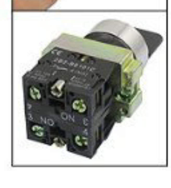
Your 3 way 2NO switches look different than mine. Mine only have 4 terminal openings but yours looks like it is stacked and has 8. Is this just a bad angle? This is the style that I have.
You can buy more contactor blocks and screw them into the bottom, the possibilities are pretty much endless.
http://www.ebay.com/itm/5pcs-TELEME...906653?hash=item5650fc68dd:g:RPUAAOxyaURTgphT
Thank you. After zooming into your photo I figured it out. I took another switch apart and realized that's what it was. I'm waiting on those parts and then I'm done the control panel. I was wondering, if I sent you a schematic of what I did with my timer, would you give it a look through just to make sure I'm good before I fire it up and fry something?You can buy more contactor blocks and screw them into the bottom, the possibilities are pretty much endless.
http://www.ebay.com/itm/5pcs-TELEME...906653?hash=item5650fc68dd:g:RPUAAOxyaURTgphT
azwillnj
Well-Known Member
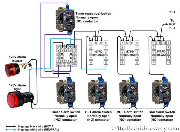
Thank you. After zooming into your photo I figured it out. I took another switch apart and realized that's what it was. I'm waiting on those parts and then I'm done the control panel. I was wondering, if I sent you a schematic of what I did with my timer, would you give it a look through just to make sure I'm good before I fire it up and fry something?
Yeah, send it over, I'll take a look.
Please forgive the roughness.
I don't think 8,9,10 are right on the timer. I followed a post on electric brewery for the timer. They switched neutral on the pids. I know my light is going to light up with the alarm but I had already drilled the hole for it so I left it in.

I don't think 8,9,10 are right on the timer. I followed a post on electric brewery for the timer. They switched neutral on the pids. I know my light is going to light up with the alarm but I had already drilled the hole for it so I left it in.

azwillnj
Well-Known Member
Sorry for the delay, it's been a really busy week. By the looks of the diagram you drew up you should be fine. The pictures look awesome too, i like the silver.
Similar threads
- Replies
- 2
- Views
- 382
- Replies
- 0
- Views
- 162
- Replies
- 2
- Views
- 389
- Replies
- 14
- Views
- 1K
- Replies
- 0
- Views
- 499


