CraftBeerPi - Raspberry Pi Software

Homebrew Talk - Beer, Wine, Mead, & Cider Brewing Discussion Forum

Help Support Homebrew Talk - Beer, Wine, Mead, & Cider Brewing Discussion Forum:

This site may earn a commission from merchant affiliate links, including eBay, Amazon, and others.
I use different. Move your sensor and tee to before your valve and then you will have live temp readings.
My temp sensor is before the ball valve, but outside the kettle. Since there is no flow during boiling (since I have the pump shut off), the temp cools down outside the kettle. I think my only options would be to put a temp sensor in the kettle or to keep the pump on.

Here's a picture of the setup:
IMG_20180501_093510.jpg
 
Like you insulate the tee somehow? You could measure the offset between in and out. Then start the lower boil percentage when the out reads the correct value.
 
My temp sensor is before the ball valve, but outside the kettle. Since there is no flow during boiling (since I have the pump shut off), the temp cools down outside the kettle. I think my only options would be to put a temp sensor in the kettle or to keep the pump on.

Here's a picture of the setup:
View attachment 568230
I put some insulation over the ball valve. It helped, but still wasn't accurate enough when the pump wasn't going. Finally moved to the kettle itself.
 
I put some insulation over the ball valve. It helped, but still wasn't accurate enough when the pump wasn't going. Finally moved to the kettle itself.
I do have a false bottom that I could put a temp probe under. Then it would be out of the way of the grain bag.
But I think I'll just run the boil with the PIDBoil Logic for now and not drill any more holes in the kettle until I know it's really what I want to do.
Or, if it's too much of a hassle to switch logic on brew day, I could just keep the pump going during boil and running the Mod_PWM logic the whole time and mess with the numbers to try and get it to have a slow rolling boil. I'm not sure if it's good for it, but those little brown pumps are supposed to be rated for boiling temp.
 
Hey ya'll, looking to pick some of your brains on a gpio failure I'm experiencing. We are running a Rpi 3, with a terragady 4.2 pcb and CraftbeerPi 3.0 with SSR's. On our third brew with the system two of our GPIO pin-outs have stopped responding to any commands from the craftbeerpi software. GPIO22 and GPIO05 are permanently switched on and receiving 12v no matter what the software is instructing them to do. We've tried reinstalling everything on the software side, but it appears to be hardware related. I've switched the SSR's and the failure persisted on those specific pins no matter what was connected to them. I haven't dissected the control box yet to directly test the pi GPIO's, but I'm curious if anyone else has experienced a failure of this type or if anyone has recommendations to try before I tear it back aprt. Thanks guys!
 
Hey ya'll, looking to pick some of your brains on a gpio failure I'm experiencing. We are running a Rpi 3, with a terragady 4.2 pcb and CraftbeerPi 3.0 with SSR's. On our third brew with the system two of our GPIO pin-outs have stopped responding to any commands from the craftbeerpi software. GPIO22 and GPIO05 are permanently switched on and receiving 12v no matter what the software is instructing them to do. We've tried reinstalling everything on the software side, but it appears to be hardware related. I've switched the SSR's and the failure persisted on those specific pins no matter what was connected to them. I haven't dissected the control box yet to directly test the pi GPIO's, but I'm curious if anyone else has experienced a failure of this type or if anyone has recommendations to try before I tear it back aprt. Thanks guys!
RasPi ar a 3.3V device, never ever connect nothing with 12V to it. If the SSR are triggered by 12V you need transistors on optocuplers in between
 
You are measuring 12v on RasPi GPIO5 pin or on the terragady output? the interfece board do what I say to separate the hi voltages from the Pi.
 
You are measuring 12v on RasPi GPIO5 pin or on the terragady output? the interfece board do what I say to separate the hi voltages from the Pi.
This would be 12vdc at the terragady outputs. I can't directly measure the pi gpio pins without disassembling my controller. Everything else is working as anticipated although I do get some interesting voltages between .5-1.5vdc when the gpio is supposedly switched off.
 
RasPi ar a 3.3V device, never ever connect nothing with 12V to it. If the SSR are triggered by 12V you need transistors on optocuplers in between
The pi is not a 3.3v device, it's 5v. The terragady board has a step down circuit that takes the input 12v and provides the pi the voltage it needs.
 
You need to adjust the voltage from the power buck to 5v

So the SSR's should not be receiving 12v from the terragady board? I thought that was a plus towards using them? Haha, anyway, I'll see what I can come up with when I take it apart I guess. Just curious why two of them suddenly stopped responding, while the other four continue to operate as expected.
 
So the SSR's should not be receiving 12v from the terragady board? I thought that was a plus towards using them? Haha, anyway, I'll see what I can come up with when I take it apart I guess. Just curious why two of them suddenly stopped responding, while the other four continue to operate as expected.
5v to the 1 wire bus and rpi, 12v to the rest. Voltage is labeled on the PCB. Many people have fried their rpi because they didn't adjust the voltage from the power buck before they plugged in the rpi
 
The pi is not a 3.3v device, it's 5v. The terragady board has a step down circuit that takes the input 12v and provides the pi the voltage it needs.

While it is true that the RaspberryPi module has a 5V power supply input the SOC is a 3.3V device and exceeding the IO pad voltage rating is a recipe for a very short life span...

Cheers!
 
Alright, so I've gotten it all torn apart and unfortunately I believe two of my terminals on the Terragady board are the problem. I've tested it three ways now:

Test1, 4.2 expansion board attached to RPi:
All GPIO actor calls off:
Pin 11 (gpio17) 0V w/ continuity Terragady gpio17- 0v
Pin 13 (gpio27) 0v w/ cont. Terragady gpio27- 0v
Pin 15 (gpio22) 0v NO CONTINUITY Terragady gpio22- 12v
Pin 29 (gpio05) 0v w/ cont. Terragady gpio05- 12v
Pin 33 (gpio13) 0v w/ cont. Terragady gpio13- 0v
Pin 37 (gpio26) 0v w/ cont. Terragady gpio26- 0v

Test 2, 4.2 expansion board attached to RPi:
All GPIO actor calls on:
GPIO's 11,13,15,29,33,37 show 0.0V/LV with no continuity when tested on the tops of the Terragady bus pins
ALL Terragady GPIO Screw Terminals show 12v

Test 3, Removed Terragady expansion board and directly tested RPi bus pins:
All pins show 0.0v with no call and 3.3v when called

Final test, ran program ~pigpio to internally test gpio function
All test returned positive with three consecutive runs.

SO if anyone is still with me at this point, pretty sure something in the pathway of the GPIO22/05 terminals on my Terragady board went ka-put! Sorry that was so many numbers... Anyone got a homebrew on tap for me?!

Thanks again for all the responses!
 
are your diodes d3 and d4 going the right way?
Yeah I'm pretty sure they are, I'll attach a picture below. I think one of my components fail. We noticed that the circuit was switched on when it wasn't supposed to be at the end of our second batch, but thought it was a programmer error on our side. Then when we started our third batch and the rims would no longer toggle on or off, we realized there was a problem. The weird part is the fact that gpio22 shows the failure when checking continuity at the pins. But both 22 and 05 are showing 12v on the expansion board. So idk if there's a component between those two circuits that might have failed and allloea them both to switch on.
 
Each pin have this circuit:

554933


You can measure voltage on the base of BC337 against ground, it should swing from 0 when gpio off to 0,7 when on. if order to see voltage swing in the output you need a load connected, a 1K resistor will do. May be the transistor is broken. The diode is there to prevent hi voltages when switching coil relays, it can be removed for ssr. watch out also for solder bridges .
You have 12V directly connected to 5V in this circuit. If you are trying to make a pull down circuit, moving the resistor the base, disconnect the 5v,place the output between the base and the moved resistor. I not sure about the need for the diode, but at least turn it around.
 
How do you solder the step down buck to the terragady board? I've google as best I could (through hole soldering without leads, through hole to through hole) and I'm as stumped as a pirate!
 
So I am interested in setting up a raspberry pi based controller. I have not read this entire thread, in the 10+ pages I have read it seems like many people have issues building one and getting it to work consistently or at all. Is it better to look at something like the hose head? Do all the components add up to close to the cost of the hose head?

I am fairly tech savvy, work in IT more on the software side. Not a lover of command line and have not built a computer since mid 90s lol. The goal would be to use the CraftBeerPi software. I am up for trying to build one if there are any clear instructions on a working version. But considering hose head if building one is close to same cost and really just a headache. Want to set something up that could do bias now but herms later.
 
Hi there;
I have a laptop gathering dust, and I want to convert it to one of these beauties you have there. Has anyone had any luck installing CBPi on a regular computer (running Arch Linux), hooked to a couple USB thermometers (on ebay) and USB relays (on ebay)? I can't see why it wouldn't work, but rather ask first. Thanks!

I have succeeded running CBPI on my Ubuntu machine with MQTT relay and temp sensors. ( Sonoff )
Not in production but for soft devel. There are references of running CBPI on a vistural machine as well.

Go for it.
 
You have 12V directly connected to 5V in this circuit. If you are trying to make a pull down circuit, moving the resistor the base, disconnect the 5v,place the output between the base and the moved resistor. I not sure about the need for the diode, but at least turn it around.
Yes , I pick that image from the thread. The line between 5V and the diode should be erased.
 
I have succeeded running CBPI on my Ubuntu machine with MQTT relay and temp sensors. ( Sonoff )
Not in production but for soft devel. There are references of running CBPI on a vistural machine as well.

Go for it.
Cheers mate. Going through the source, it seems that it's quite modular, and I can just define my "actors" and "thermometers". Gorgeous. Well, I'll go for it indeed! Thanks!
 
You have 12V directly connected to 5V in this circuit. If you are trying to make a pull down circuit, moving the resistor the base, disconnect the 5v,place the output between the base and the moved resistor. I not sure about the need for the diode, but at least turn it around.
Wow I was was off when I wrote this. Like you later mentioned, simply disconnect the 5V from the 12V. Also make sure your motor/relay etc is connected through the 12V to the BC337. If you are not seeing it turn on you can lower the base resistance (R1) to increase the current draw.
 
Are people finding v3.0 is working well? I tried it last weekend for a brew day. I really wanted to use the PWM setting for my RIMS tube. Part way into my mash it stopped controlling the element. Once the element turned on it would just keep heating and not shut off at setpoint. It also didn't seem to want me to toggle the control button (The one with the car on it). I ended up manually running the element for the rest of the mash with the power button just to stay at temp.

Any idea what I might have done wrong? Is there a plug in that lets v2 do PWM for a heating element?

It may not be your problem but maybe something to check... most cheap SSR's, Fotek etc.. you find on the internet are fakes.
I had a SSR that would stay latched at 100% after a long on period like bringing water up from room temp (HERMS System) although the software was in PWM mode.
If I turned it off for a bit and restarted it would PWM correct for a while but it sure drove me crazy a few brew days.
At the time I was not using Craftbeer PI but the PWM worked the same.
Now I use Crydom SSR's and haven't had a issue with it getting latched on.
If you have a meter with a duty cycle setting you can easily monitor the DC+ side of the SSR and see if is hardware or software.
I could see the SSR on system latched on by the AMP gauge not moving, temp on target and staying at 23 amps.

Cheers
 
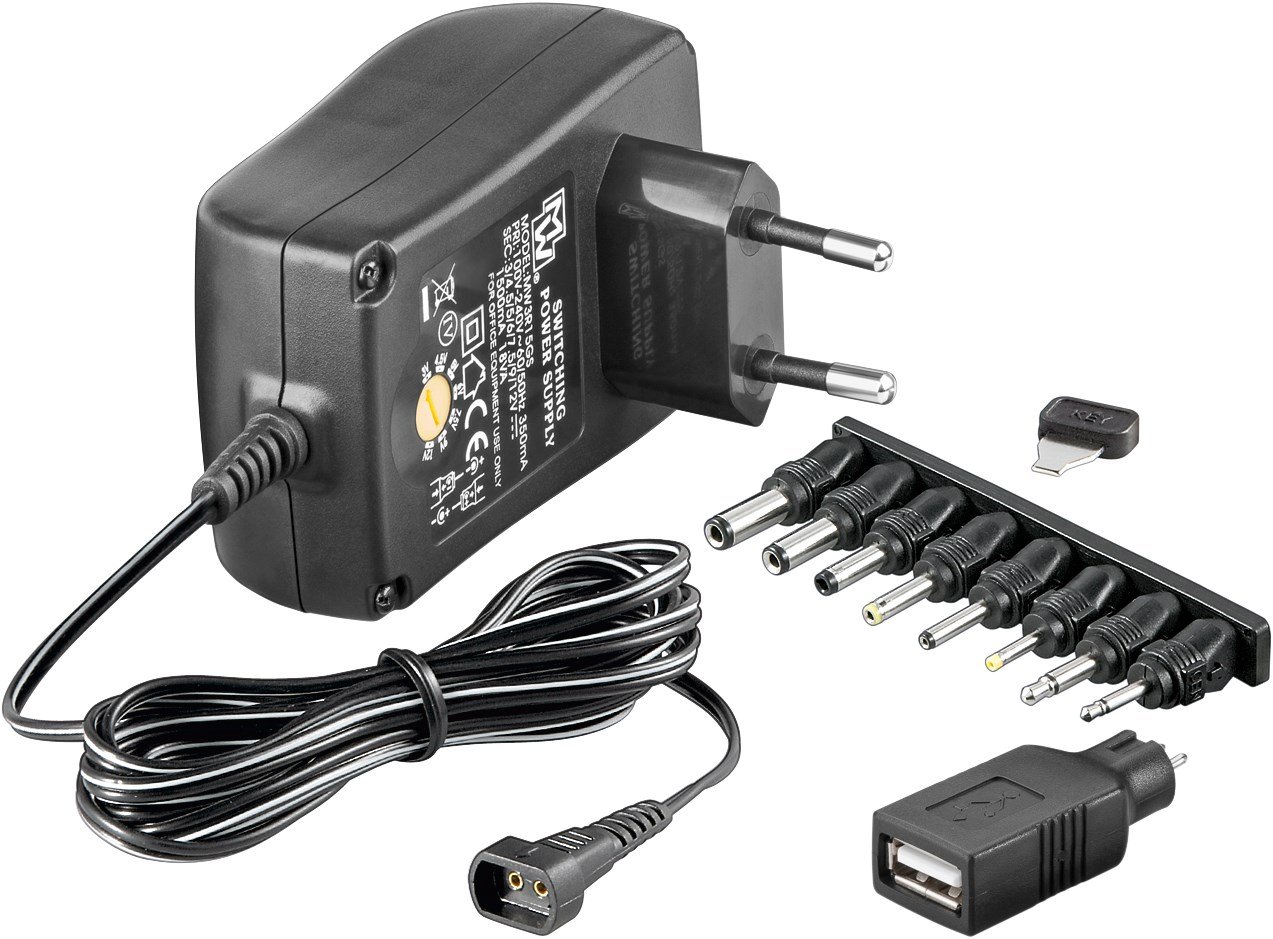
Using the terragady shield, can I supply the 12v via a universal dc power supply that goes up to 1.5A? Or is that too little considering the Pi needs 2.5A? Looking at one of these:
71N7FT0G0uL._SL1273_.jpg
 
It may not be your problem but maybe something to check... most cheap SSR's, Fotek etc.. you find on the internet are fakes.
I had a SSR that would stay latched at 100% after a long on period like bringing water up from room temp (HERMS System) although the software was in PWM mode.
If I turned it off for a bit and restarted it would PWM correct for a while but it sure drove me crazy a few brew days.
At the time I was not using Craftbeer PI but the PWM worked the same.
Now I use Crydom SSR's and haven't had a issue with it getting latched on.
If you have a meter with a duty cycle setting you can easily monitor the DC+ side of the SSR and see if is hardware or software.
I could see the SSR on system latched on by the AMP gauge not moving, temp on target and staying at 23 amps.

Cheers
The SSR works fine engaging the element and shutting off. The indicator light on the SSR appears to be operating normally with the state indicated on the Pi.

This is clearly something with the software that is locking up and not operating the algorithm. In the middle of the brew session.
 
To any developers out there - a SDK for CBPi3 was just released called swill-sdk. The repo's wiki fully documents swill's API. If you are interested in making your own front end for CBPi3, or extend or integrate it in some way that you'd previously been limited in, this may be your ticket:

https://github.com/jonrhall/swill-sdk
 
Yes , I pick that image from the thread. The line between 5V and the diode should be erased.

FYI - the 12v in that pic is the "marking" on the board, not the actual voltage. (the drawing was used to show how to use the boards with just a 5v supply only, no 12v anywhere)

You are correct, for a normal board being fed 12v and supplying 5v to the Pi, that portion of the line would be erased.
 
This may not be the proper place for this post but I have a question for the folks I've seen on here in the past that make CraftbeerPi boards. Do any of you do one off/ custom boards? I have a fairly simple, at least in my mind, board I've been trying to put together in order to use a ULN2803 or ULN2804 between my Pi and SSR's, etc, depending on the power supply I chose. Normally I'd do it myself put I had a minor stroke a while ago and, while it's just a slight inconvenience for most day to day things, my fine motor skills don't cut it any more. I've tried several times to put this thing together but I always end up with solder bridges. This is the circuit I'm trying to put together. Please excuse the crude drawing. I downloaded one of those circuit design programs so I could better show my intentions but in spite of those people who say you "can" actually teach an old dog new tricks I'm sadly not a dog.

DIN socket2.jpg
I'm not looking for a fancy silk screened board. It doesn't have to be pretty, only functional. A DIN socket on a perf board with the screw terminals and possibly, if it doesn't increase the cost too much, an LED on each "IN" from the Pi to know it's working. I honestly have no idea what something like this would cost and being an old retired guy this is a concern but if someone can do this I'd pay whatever they think their knowledge, time and materials are worth.
 
This may not be the proper place for this post but I have a question for the folks I've seen on here in the past that make CraftbeerPi boards. Do any of you do one off/ custom boards? I have a fairly simple, at least in my mind, board I've been trying to put together in order to use a ULN2803 or ULN2804 between my Pi and SSR's, etc, depending on the power supply I chose. Normally I'd do it myself put I had a minor stroke a while ago and, while it's just a slight inconvenience for most day to day things, my fine motor skills don't cut it any more. I've tried several times to put this thing together but I always end up with solder bridges. This is the circuit I'm trying to put together. Please excuse the crude drawing. I downloaded one of those circuit design programs so I could better show my intentions but in spite of those people who say you "can" actually teach an old dog new tricks I'm sadly not a dog.

View attachment 574884 I'm not looking for a fancy silk screened board. It doesn't have to be pretty, only functional. A DIN socket on a perf board with the screw terminals and possibly, if it doesn't increase the cost too much, an LED on each "IN" from the Pi to know it's working. I honestly have no idea what something like this would cost and being an old retired guy this is a concern but if someone can do this I'd pay whatever they think their knowledge, time and materials are worth.

How about this: https://PCBs.io/share/zk7Px
 
This may not be the proper place for this post but I have a question for the folks I've seen on here in the past that make CraftbeerPi boards. Do any of you do one off/ custom boards? I have a fairly simple, at least in my mind, board I've been trying to put together in order to use a ULN2803 or ULN2804 between my Pi and SSR's, etc, depending on the power supply I chose. ...

The Terragady v5 board does 8 transistor outputs already, 6 on screw terminals and 2 on pin headers, with a bonus of a spot for a buzzer, one wire temp probes, an I2C bus, AND a 12v to 5V converter (you can also power it with 5V if needed) All that and the price is ridiculously cheap compared to a custom board. It does not have LED's, but a simple and cheap 8-relay board has them, as do most SSR's.
 

Latest posts

Back
Top