PSA: Try Powering Your Uncooperative DS18B20s Via 5V

Homebrew Talk - Beer, Wine, Mead, & Cider Brewing Discussion Forum

Help Support Homebrew Talk - Beer, Wine, Mead, & Cider Brewing Discussion Forum:

This site may earn a commission from merchant affiliate links, including eBay, Amazon, and others.

kdw2pd

Well-Known Member
Joined
Dec 27, 2013
Messages
202
Reaction score
39
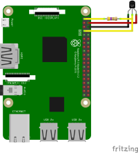
I've been struggling with getting a Pi 4B to recognize some cheap Amazon DS18B20s. I was powering them via 3.3V, and getting the "00-80000000" result in /sys/bus/w1/devices. After scrounging a bit, I found a few references to folks powering them via 5V. Tried it out, and voila, "28-", reading temps, and CraftBeerPi has a kettle sensor once more. So I figured I'd throw this up here to make it easier for someone else to find in the future.

Attached is a wiring diagram of what worked for me (source: A DS18B20 with 5v - Raspberry Pi Forums). Make sure to include the 4.7K pullup resistor between 3.3V and data.
 

Attachments

  • Rpi DS18B20 5V Wiring.png
    Rpi DS18B20 5V Wiring.png
    89.4 KB · Views: 0
Congrats on figuring this out, I've been prescribing it on our numerous controller threads for years :)
Also, you can use up to a 2.2K ohm pull-up resistor when referencing it to 3.3V, which can be handy for long or multi-dropped topologies...

Cheers!
 
Now ya tell me! I looked quickly through a couple of HBT CBPi threads and didn't see that!
 
You'd want to look in the threads for RaspberryPints and especially BrewPi and its derivatives.
Not the most active these days, though, so having it just pop up in recent conversation isn't likely anymore...

Cheers!
 
I would not put 5 volts onto a Pi IO pin.
I had the same issue when using 4k7 pull up resistors on 3.3 volt microcontrollers.
Reducing the 4k7 to 2k2 resolved all the problems while keeping the DS18B20 supply at 3.3 volts
 
You're missing what's going on: the DS18B20 gets its VCC at 5V, but its output is OPEN DRAIN so it cannot drive high, it can only PULL DOWN - it can only assert a "0" and relies on the resistor pull-up to provide a "1". That pull-up resistor in turn is referenced to 3.3V - the same voltage as the RPi VCCIO - so no damage can occur.

Cheers!
 
you are quite right,I looked again at the diagram and see that.
I assumed the pullup resistor was also connected to 5v supply which would have put 5v onto the IO pin.

Cheers
 
I'm wondering if this would this fix my problem. I've got a Hosehead controller and when I added some more temp sensors some of them stopped working. Now I'm down to only 2 of them working at all and sometimes I have to reboot it mid brew session to get them both back. It's frustrating but this might be my solution.
 
The more sensors one has on a One-Wire network the greater the capacitive loading from the sensors and wire which slows positive edge rates (the transitions from 0s to 1s). If slow enough that can confuse devices sharing the signal line. On a 3.3V signaling network (ie: connected to RPi or ESP IO pins) changing the pull-up resistor from say the nominal standard 4.7k ohms to 3.3k or even 2.2k will increase the positive edge rate and may clear up intermittent comms problems with no down-side risk...

Cheers!
 
When many devices are in the bus the length of wire also plays.
Some times adding or cutting 20cm on a sensor make all work.
As per spect sheet the pull down current could be up to 7mA. On 3.3V the limit is 470 ohms.
I have many buses with 8 or 10 sensors to the RPi with 820 ohms pull up working ok for years.
 
ok - so how do I make that happen on my Hosehead controller? I am no electrician and a complete danger with a soldering iron lol. I have a pile of about 20 of these sensors after buying a bunch to replace the ones that quit working. Maybe they weren't bad to begin with?
 
Unless proven otherwise it is certainly possible some sensors you may think were failing are actually good and they just didn't like the environment.

Given a collection of unknown sensors, the sanest approach is to test sensors one at a time before connecting together the ones that work singly. Saves hair ;) Then you just have to validate that the collection will play nice together - and that may indeed mean changing the resistor pull-up value to optimize the network performance.

I know zilch about the Hosehead controller. Did it use an RPi "shield" or a stand-alone PCB? If you have a schematic diagram of a Hosehead controller the identity of the One Wire pull-up resistor should take just a moment to spot. It literally should be the only resistor connected to the RPi IO pin used for "One Wire Data" or equivalent...

Cheers!
 
ok - so how do I make that happen on my Hosehead controller? I am no electrician and a complete danger with a soldering iron lol. I have a pile of about 20 of these sensors after buying a bunch to replace the ones that quit working. Maybe they weren't bad to begin with?
First thing try each one alone in the RPi, throw away the ones not working.
Then remember one wire bus do not like star configuration. Is better tho have 3 wires going around and atache the sensor to that line with short wire.
Take a look in hear : https://www.analog.com/en/resources...es-for-reliable-long-line-1wire-networks.html
 
Back
Top