List of PJ Electrical Diagrams

Homebrew Talk - Beer, Wine, Mead, & Cider Brewing Discussion Forum

Help Support Homebrew Talk - Beer, Wine, Mead, & Cider Brewing Discussion Forum:

This site may earn a commission from merchant affiliate links, including eBay, Amazon, and others.
I like the idea of using a knob to control the boil vs. a PID's manual-mode much like HighGravity's EBC SV with Infinite Power Control.

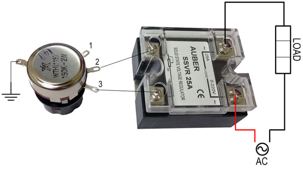
I'm looking for guidance on using a SSVR in P-J's "Single Element BIAB 30A PID" circuit?

I think I'd need to use a PID with Relay output (2342?) and I'd need to move the SSVR between the contactor and element.

Would this allow the PID to drive the contactor for temperature controlled mashing?

I believe I'd also need a 3-way switch that would allow the contactor to be energized by either the PID (for mashing), Manual (for boil), or Off.

The SSVR knob would be set to 100% for the mash and adjusted accordingly to control the boil.

Thanks in advance
:mug:
 
Seems I can't find a 1500w 240v LWD heating element so the next best thing is a 2000w LWD element for my rims tube. Would I still be able to run both elements using this wiring design here? Also would there be a way to run rotary switches instead of toggle switches and if so could someone link me to some please. Thanks in advance


Auberin-wiring1-a13-SYL-2352-4500w-RIMS by Ludahchris, on Flickr
 
Hello,
I just thought that I would share the diagram that P-J did for my custom build with the hope that others may benefit from it as we'll.

image.jpg
 
Here is the control panel to go with it. It is not wired yet because I decided to add pilot lights and use 30Amp supply rather than 50Amp so I will need to view other diagrams to make these changes. Thanks again P-J.

image.jpg
 
P-J,

We are building a 30 gallon 3 vessel E-HERMS system and could use some help laying out the controls. The HLT and BK both have 2 - 5500w elements and we are thinking that we would like to able to operate 2 HLT, 1 HLT+1 BK, or 2 BK simultaneously. Trying to keep the total load under 60A 220V. We are going to use a BCS-462 controller but we like the auto/manual option you have incorporated into other designs. Additionally, we have two 120V pumps (separate water and wort). We plan to have a touch screen mounted on the panel for BCS control and temp/time readout.
 
First, I just want to say awed I am with the generosity of P-J, The number of drawing, the time spent thinking about all of the considerations for each of the systems. There needs to be an award for someone who has contributed so much. Thank you.

Also, to have all of the drawings on a single page is mind bending. When I found the page I had a very narrow focus on what I thought I wanted. After seeing all of the drawings, which represent very different systems, I am now considering adding a sub-panel to my house so I don't have to be restricted by power.

I am not thinking of building a big system, but I want to be sure to not cut corners so next year I am not doing what I'm doing now. I will be ditching my propane system for an electric one.

I currently brew 2.5 gallon batches, but I do many of them. I usually have 8 or more different beers available at a time so the system needs to be easier to setup and clean. I started thinking I would build a recirculating eBIAB system, but now I might just build a more traditional 3 kettle system with a herms coil. I need to spend some time understanding the value add, other then the fun of building it, of the traditional mash process over the BIAB process before I commit to one.

This is an awesome page full of so many options, Thank you P-J for all of your work.
 
Been a long time since I posted here because I kind of gave up on the idea of going electric. Well now I'm back too it!

Does anyone know of a diagram that PJ might have made that replicates the EBC III Design from High Gravity?

I'm going to start off using 3 vessel and w/ cooler mash tun and no HERMS but want to ability to expand to a HERMS setup. I like the variable control knob on this unit for the boil, and the 2nd PID controlling the pump power for the HERMS unit.
 
Hi I was wondering if anybody has a diagram for a 50 amp 2 5500 elements a 2000 rims 1 timer 3 pid 2 plugs for pumps ? Also maybe even a list of what to purchase? Thanks
 
I was looking for the same type of drawing as Rowdy. 2 5500W elements for Boil & HLT, 1 2000W RIMS; 3 PID's and 1 timer. Thanks,
 
Hi I was wondering if anybody has a diagram for a 50 amp 2 5500 elements a 2000 rims 1 timer 3 pid 2 plugs for pumps ? Also maybe even a list of what to purchase? Thanks
I've not made a diagram for what you describe. I've done one without the timer though. I will come up with one, just give me a couple of days to draw it for you.

Something to keep in mind. You are planning on 2 - 5500W elements & a 2000W element. That is a total of 13000W running on 240V. That ends up being a possible draw of 55A plus the control circuits and pumps. You might need to have a 240V 60A feed (plus a 60A Spa Panel from HomeDepot) to power your rig.

P-J
 
P-J said:
I've not made a diagram for what you describe. I've done one without the timer though. I will come up with one, just give me a couple of days to draw it for you. Something to keep in mind. You are planning on 2 - 5500W elements & a 2000W element. That is a total of 13000W running on 240V. That ends up being a possible draw of 55A plus the control circuits and pumps. You might need to have a 240V 60A feed (plus a 60A Spa Panel from HomeDepot) to power your rig. P-J
Do a 1500w I've already run 50 amp spa. Thanks
 
Do a 1500w I've already run 50 amp spa. Thanks
I think you will be hard pressed to find a 240V 1500W element. Plus it will still be over the total or your 50A feed. I suggest that you consider 2-4500W element and the 2000 element. With that config your draw is under 50A.

Just saying...
 
P-J said:
I think you will be hard pressed to find a 240V 1500W element. Plus it will still be over the total or your 50A feed. I suggst that you consider 2-4500W element and the 2000 element. With that config your draw is under 50A. Just saying...
Okay thanks.
 
PJ if I drop to 4500W elements would it affect boil time much. If I did that the current draw would be 46 amps. Would it be better to go to a lower wattage RIMS element? Thanks, Joe
 
Okay thanks.
Talk more about your desired process flow. You will never need all three on at the same time.
PJ if I drop to 4500W elements would it affect boil time much. If I did that the current draw would be 46 amps. Would it be better to go to a lower wattage RIMS element? Thanks, Joe

I completed the diagram today. The configuration is set up with 2-5500W and a 2000W RIMS element. (BTW You would have a difficult time securing a lower wattage RIMS element.) The system, depending on your brewing process, can be used that way. You would just need to use the BOIL element independently as you brew. You also could change the 2 5500W elements to 4500W elements if your intent was to do back to back brew sessions where you would need the HLT, RIM & BOIL at the same time.

Anyway - as always - click on the image to see (and save) a full scale diagram printable on Tabloid paper (11" x 17")


I hope this helps you in your adventure.

P-J
 
I am planning to start acquiring the necessary parts to start my electric build. I was thinking that the 50a 5500 2 element 2 pump 2 PID looks the closest to what I would like to do. However, I am a little uncertain what a couple of the parts are. What are the parts between the Contactor at the element and the PID’s, not the switches but the other parts? Also, the Contactor is listed as “240V – 30A 120 V Coil”. Are they the Auber CN-PBC302-120V?
 
I am planning to start acquiring the necessary parts to start my electric build. I was thinking that the 50a 5500 2 element 2 pump 2 PID looks the closest to what I would like to do. However, I am a little uncertain what a couple of the parts are. What are the parts between the Contactor at the element and the PID’s, not the switches but the other parts? Also, the Contactor is listed as “240V – 30A 120 V Coil”. Are they the Auber CN-PBC302-120V?
The part you are referencing is a SSR. Here is a LINK to it from Auber Instruments.

The contactors are the ones you referenced.

P-J
 
The part you are referencing is a SSR. Here is a LINK to it from Auber Instruments.

The contactors are the ones you referenced.

P-J

Thank you so much. Is there a temperature sensor/thermocouple sensor you would recommend? I was planning on putting them outside the ball valve on the pots like Kal and not in the side of the pot.
 
Thank you so much. Is there a temperature sensor/thermocouple sensor you would recommend? I was planning on putting them outside the ball valve on the pots like Kal and not in the side of the pot.
Auber Instruments has several different types and sizes available. Here are 2 deluxe probes as a reference:
Liquid tight RTD sensor, 4 in, 1/4 NPT
And
Liquid Tight RTD Sensor, 4” probe, Weldless Fitting

You have lots of options from their available products. RTD (PLT) Sensors

Hope this helps.

P-J
 
PJ, Thanks so much. I intend on doing single 10 gallon batches right now, but wanted the possibility of back to back batches. It seemed like a better option to look at the needs I would have in the future, and buy & build once.

Bobby, thanks for your input. I was thinking of the process, not in the present; but for future growth.

Thanks again,
Joe
 
If I decided step up to use 2500w a 5500w element on my 30 amp 240v wiring setup instead of a 1500w and a 4500w element and only use one element at a time will it still be safe to use this wiring diagram or would I have to change something around?
You could do that but I'd suggest that you interlock the setup so that you can not energize both elements at the same time.
 
Thanks for the reply PJ. Because of you and your drawing I have ordered and received about 90% of all my parts needed with more on the way and will be building my RIMS system on my 2 week vacation next week! One more question though, what size wire would be ok to use from the ssr to the pid? If 10g is needed then how would you wire up the connection to the pid since the screws and space are so small.
 
Thanks for the reply PJ. Because of you and your drawing I have ordered and received about 90% of all my parts needed with more on the way and will be building my RIMS system on my 2 week vacation next week! One more question though, what size wire would be ok to use from the ssr to the pid? If 10g is needed then how would you wire up the connection to the pid since the screws and space are so small.

You are on an exciting adventure. I wish you the best success.

The wiring plan: Use stranded wire for all of your setup. Use #10 for the input to your controller. The ciruits to the elements should be #12. The circuits to the pumps and PID power can be #14. The lines from the PID outputs to the SSRs and flash buzzer can be fairly small as the current draw there is very small (Less than an amp each), perhaps #16 or #18.

I hope this helps you. Also, if you need other info or changes to your plan please le me know.

P-J
 
I guess that explains why the screws and slots are so small on the PID's. Once again I thank you and I'm sure I'll have more questions along the way here soon. A little overwhelming right now but it will all fall in place once I get started. I don't really understand how the interlock works and how it would work in my system so I'll just make sure to only power on one element at a time.
 
I guess that explains why the screws and slots are so small on the PID's. Once again I thank you and I'm sure I'll have more questions along the way here soon. A little overwhelming right now but it will all fall in place once I get started. I don't really understand how the interlock works and how it would work in my system so I'll just make sure to only power on one element at a time.

If needed, I can adjust the diagram to include an interlock or any other changes that you might need or want.

Just saying. I think this old man can wrap my head around your plan.

(LOL)

P-J
 
If needed, I can adjust the diagram to include an interlock or any other changes that you might need or want.

Just saying. I think this old man can wrap my head around your plan.

(LOL)

P-J

If you are bored stop by my three pronged outlet thread and look at my last entry to see if you could throw some input my way. :)
 
Is there a wiring diagram available for a simple controller like this:

http://www.highgravitybrew.com/productcart/pc/viewPrd.asp?idproduct=3084&idcategory=306#.Ul8R2xByZX8

No PID or pumps involved and just a single 5500w element.

Thanks

That unit appears to be a very simple power delivery system similar to the components offered by Auber Instruments.

25A Solid State Voltage Regulator SSVR

The setup looks like this:

SSVR25A.jpg


If you choose to use this, be sure to click on the Please Choose: Rheostat Option (Pull down)

(SSVR Only - without Rheostat
For 120V AC, 60Hz
For 240V AC, 60Hz )

I'm sure this would work out for you.

P-J
 
If your willing to take the time to add the interlock that would be great and I won't turn the offer down at all! I will be switching out the RIMS heating element for a 2500W Camco lime life element and the 4500W element for a 5500W element if that changes anything? I also added 2 indicator lights one each between the switches and the elements and 2 indicator lights for the pumps.
 
That unit appears to be a very simple power delivery system similar to the components offered by Auber Instruments.

25A Solid State Voltage Regulator SSVR

The setup looks like this:

SSVR25A.jpg


If you choose to use this, be sure to click on the Please Choose: Rheostat Option (Pull down)

(SSVR Only - without Rheostat
For 120V AC, 60Hz
For 240V AC, 60Hz )

I'm sure this would work out for you.

P-J

Thanks PJ!

I am not going to buy this from high gravity. I am going to try to build something similar, I just don't know very much about electrical. That is why I asked for a diagram.

I didn't see a "Please choose rheostat" option. Only cord type/length and receptacle type.

Just to be clear: The "AC" on the diagram is for the plug seen on the box where the element would plug in correct? Where would the wire from controller to the wall be located?
 
PJ

I have a 120v, duel element boil kettle build in progress and I got the crazy idea that I needed to add a RIMS system to it. I looked through your list of drawings and I could not find an example of what I looking to do. I then dug through every topic in the Electric Brewing and finally found something similar to what I would like. It is not one of your drawings, but I was hoping I could get at least get your opinion on it. If it isn't asking too much, I would really appreciate some help with a redesign, as there are several things I would like to do differently. A link to the drawing I found is attached below. It is a 2 circuit, 2 PID system that runs two 2000w elements on a BK and a 1500w element in a RIMS.

In my ideal build, I would like the 2 PIDs to each have a green LED push button switch. One of the boil kettle elements would be controlled by an On/Off selector switch with a yellow LED indicator light. The 2nd boil kettle element and the RIMS element would be controlled by an On/Off/On selector switch and have two yellow LED indicators to show which element is being powered. I'd like two blue LED push button switches for a Pump and an Auxiliary outlet (most likely a future pump). The original drawing is set up so that the RIMS element can not run unless the pump is on. While this is an excellent idea, I want to run the pump at the same time as both boil kettle elements, so I plan to break that tie for now . I would also like to include an emergency stop switch.

https://www.homebrewtalk.com/attach...element-120v-control-panel-wiring-diagram.pdf
 
Thanks PJ!

I am not going to buy this from high gravity. I am going to try to build something similar, I just don't know very much about electrical. That is why I asked for a diagram.

I didn't see a "Please choose rheostat" option. Only cord type/length and receptacle type.

Just to be clear: The "AC" on the diagram is for the plug seen on the box where the element would plug in correct? Where would the wire from controller to the wall be located?

I didn't see a "Please choose rheostat" option.
Look at the "Add to Cart" block. There is a pull down for you to choose from labeled: "Please Select".
 
Paul,

Thank you for your kind words.
Here is a diagram that I just finished for you as I did not have one that really fit your description. I hope it matches your needs.

And as always - click on the image to see (and save) a full scale diagram printable on Tabloid paper (11" x 17")


I hope this helps you in your adventure.

P-J

P-J,
I've got all my parts purchased and on their way! Thanks for diagramming this for me.

I've got a question that I hope you could help me out on though....

I've got a toolbox pump that I use and would like to incorporate into this control panel build. The pump uses a GFCI outlet, and a 2 Gang switch (one for main power, one to turn on pump) The outlet is wired in on the back to power a 3 bank power strip that I plugged my pump into. How would I wire/rewire the pumpbox to run separately of the control panel, but also run when plugged into the control panels pump outlet?

Any takers?!
 
Back
Top