I’m in the process of wiring my control box and I had few questions.
A friend has written a program for the Raspberry Pi that controls all the processes and it’s run through a tablet (or some device, I haven’t got that far yet).
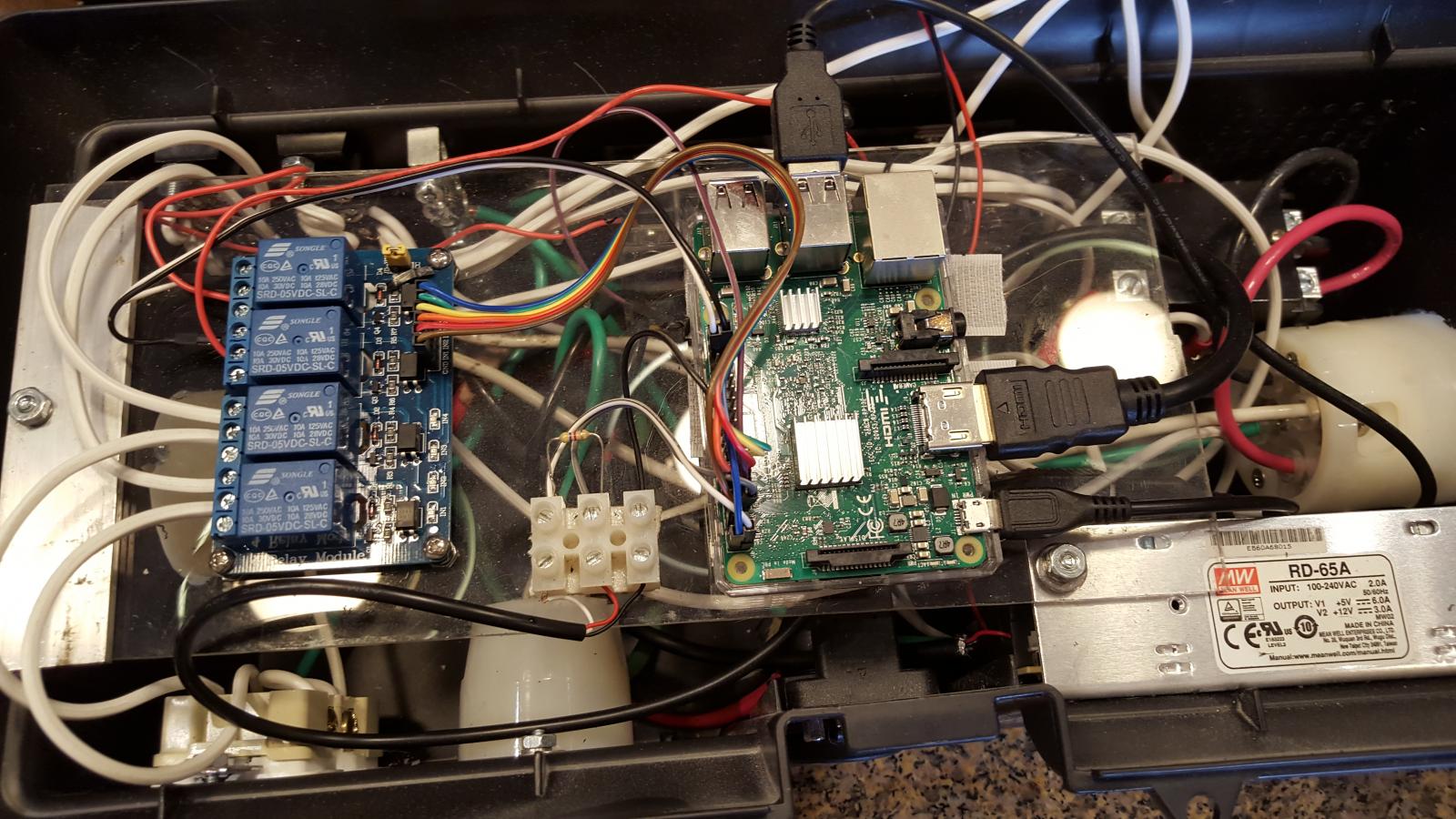
Anyhow, here’s my current wiring (without the Raspberry Pi):

Any obvious faults other than what I mention below?
The first thing is that it doesn’t have any contactors/relays that completely cut off the SSR’s. The Raspberry Pi only has an output of 3.3 volts. It can operate the SSR’s but, other than SSR’s, I can’t find any relays that will handle 220 volts and a coil that can be operated with 3.3 volts. Any suggestions? I can add a switch to the box and two contactors but this defeats some of the functionality of using a Raspberry Pi.
The program can also turn the pumps on and off. But again, I can’t find any contactors/relays that will work other than an SSR. Would an SSR be a good choice for a relay to run a pump? I’m concerned about the amount of heat generated when up to three SSR’s are all running at the same time. The other option would be to just add a couple of switches to the control box but again this defeats some of the functionality of using a Raspberry Pi.
I used 220 volt indicator lights but as I was looking at this again, I realized that I probably could have used 110 volt lights (and 14 AWG wire instead of 10) if I had wired them up with the black lead and the neutral (white) something like the diagram below. Can I do it this way? Should I use a fuse for this? If so, can it be on the neutral side so I only need one rather than on the hot side where it would take 3?

Thanks for any input. I’m really trying to understand how this will work. This forum has been very helpful with this.
A friend has written a program for the Raspberry Pi that controls all the processes and it’s run through a tablet (or some device, I haven’t got that far yet).
Anyhow, here’s my current wiring (without the Raspberry Pi):
Any obvious faults other than what I mention below?
The first thing is that it doesn’t have any contactors/relays that completely cut off the SSR’s. The Raspberry Pi only has an output of 3.3 volts. It can operate the SSR’s but, other than SSR’s, I can’t find any relays that will handle 220 volts and a coil that can be operated with 3.3 volts. Any suggestions? I can add a switch to the box and two contactors but this defeats some of the functionality of using a Raspberry Pi.
The program can also turn the pumps on and off. But again, I can’t find any contactors/relays that will work other than an SSR. Would an SSR be a good choice for a relay to run a pump? I’m concerned about the amount of heat generated when up to three SSR’s are all running at the same time. The other option would be to just add a couple of switches to the control box but again this defeats some of the functionality of using a Raspberry Pi.
I used 220 volt indicator lights but as I was looking at this again, I realized that I probably could have used 110 volt lights (and 14 AWG wire instead of 10) if I had wired them up with the black lead and the neutral (white) something like the diagram below. Can I do it this way? Should I use a fuse for this? If so, can it be on the neutral side so I only need one rather than on the hot side where it would take 3?
Thanks for any input. I’m really trying to understand how this will work. This forum has been very helpful with this.