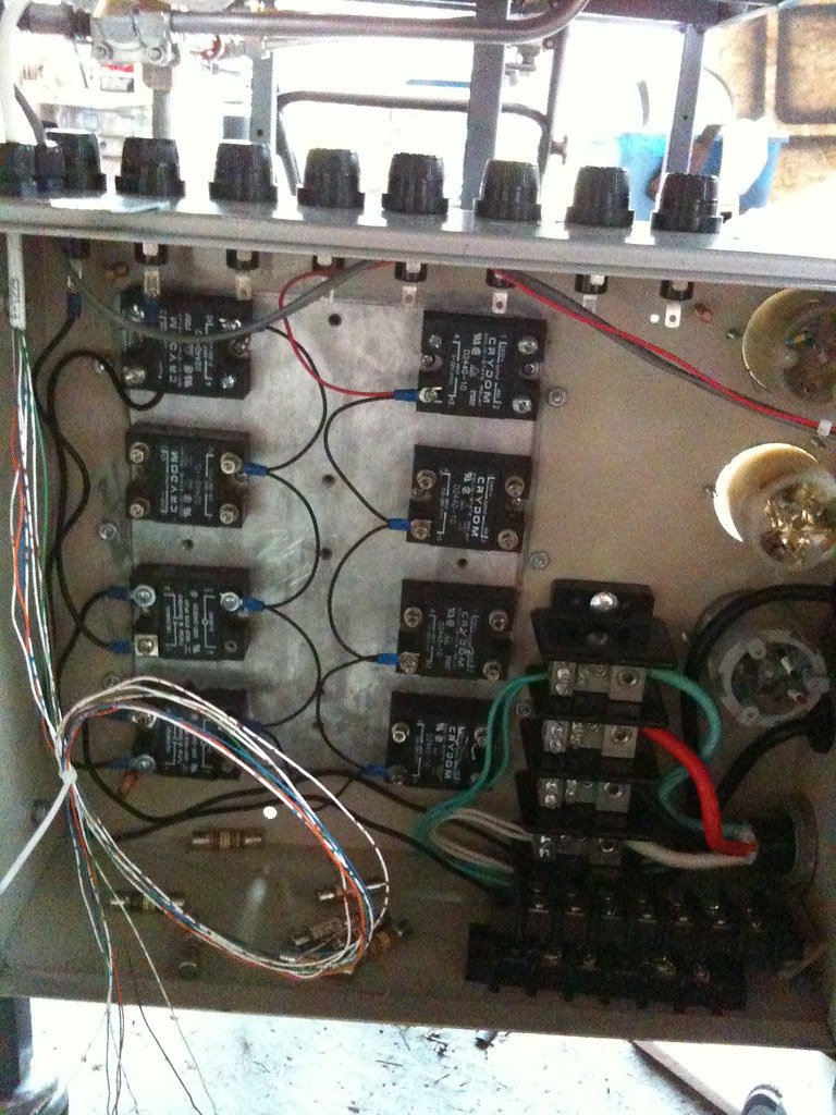
I am really confused about fusing and distribution of 50A service in my brew rig's control panel.
My equipment:
50A - 240V, 6AWG feed from GFCI Breaker
(6) 40A SSR
(2) 25A SSR
(1) 12v power supply
(2) 4500W element
(1) 3500W element
(2) 1/3 hp pumps (3A draw each)
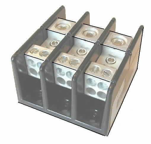
(1) 4-pole distribution block (each input post has 6 output posts)
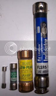
(2) 2-pole fuse holder
(10) single fuse holder
distribution block
fuse holder
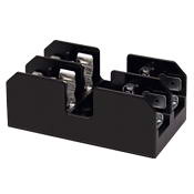
single fuse holder
I don't understand why the distribution block accepts large wire sizes on the input side and reduces them to smaller gauge wire on the output without fuse protection. I need some help laying this thing out. What would be the best way to run 240v to each element's SSR, 110v to each pump's SSR and 110v to the power supply?
My equipment:
50A - 240V, 6AWG feed from GFCI Breaker
(6) 40A SSR
(2) 25A SSR
(1) 12v power supply
(2) 4500W element
(1) 3500W element
(2) 1/3 hp pumps (3A draw each)
(1) 4-pole distribution block (each input post has 6 output posts)
(2) 2-pole fuse holder
(10) single fuse holder
distribution block
fuse holder
single fuse holder
I don't understand why the distribution block accepts large wire sizes on the input side and reduces them to smaller gauge wire on the output without fuse protection. I need some help laying this thing out. What would be the best way to run 240v to each element's SSR, 110v to each pump's SSR and 110v to the power supply?
")