lgxg
Well-Known Member
I'm working on putting together a RIMS control panel. I will have one PID, a 1500 watt element and will be running on 120v. I will also have one pump, but may add another in the future. The lower wattage element and the fact that I did not incorporate the e-stop that leaks a tiny bit of current into the GFI are the only differences from my use case and wiring.
I found this wiring diagram a while back that was created by PJ, and is hosted on his site: http://www.pjmuth.org/beerstuff/images/Auberin-wiring1-SYL-2352-basic5-RIMS.jpg
I spent a lot of time this afternoon wiring up the switches PID, etc. I got all the PID/SSR connections done and all of the blue wires except for one or two.
1. On the main power switch (red) - there is an input from the hot wire that goes into 23 and 13. Does anyone have an idea on how to split this one line to get it into both places on this switch? pigtail and wire nut?
1a. I guess the same applies for the neutral (yellow line) that runs from the terminal block into the pump switch and then into the PID. I'm thinking about using 18 gauge again here for simplicity.
2. For the LEDs on the hot wire, where x2 was connected to 24 or 14 on the switch, I just used a little bit of 18 gauge wire with a spade connector. Is this ok?
3. I am thinking about using a wire nut for the grounds instead of a terminal block. Would this be ok? As I mentioned I am not doing the emergency shut off that leaks current into the GFI. So the three wires will be from the incoming power going into the wall, the pump receptacle and RIMS receptacle.
4. This one's for PJ (if you're out there and have some time) what would it look like to add another switch (same type) and receptacle for another pump? This one would just be for moving water from the HLT to the MLT for sparging. So - it wouldn't need interlock the heat setting like the main/RIMS pump.
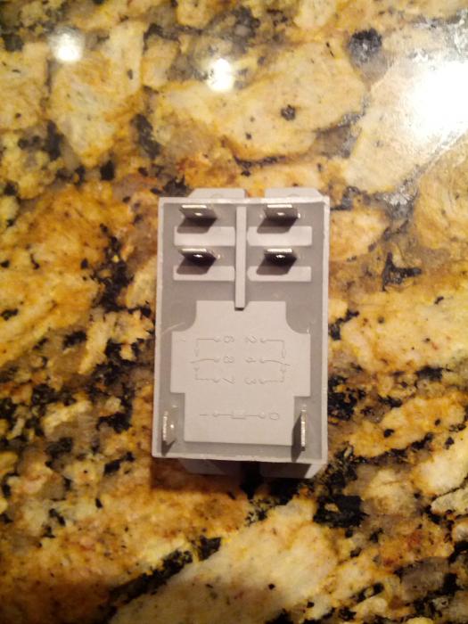
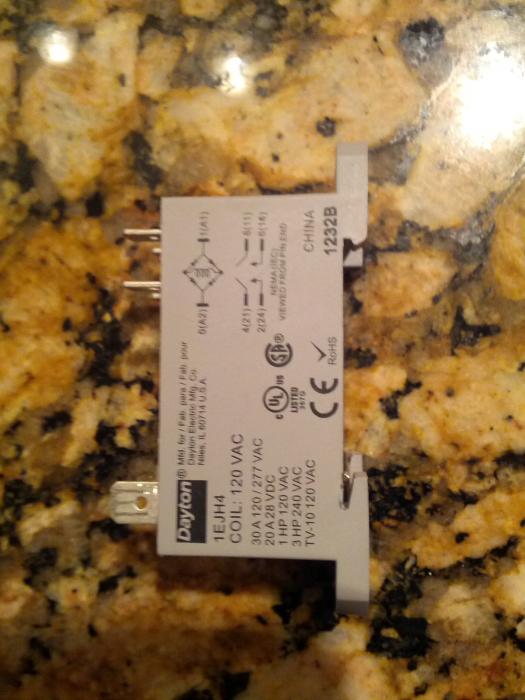
5. about the Contractor. I am not sure what to wire where. I know which side is the coil (with the two opposing connections, but I'm not sure which ones to wire neutral and which ones to wire hot from the heat switch and SSR output. I have included a photo. this newbie can't tell which way is up on this thing when reconciling to the wiring diagram...
Thanks everyone! This has been a really fun build. I couldn't have done it without all the help in the awesome community.
Louis


