Wire Diagrahm 1 PID 2 Element

Homebrew Talk - Beer, Wine, Mead, & Cider Brewing Discussion Forum

Help Support Homebrew Talk - Beer, Wine, Mead, & Cider Brewing Discussion Forum:

This site may earn a commission from merchant affiliate links, including eBay, Amazon, and others.

Wolfairious

Well-Known Member
Joined
Jan 11, 2015
Messages
101
Reaction score
22
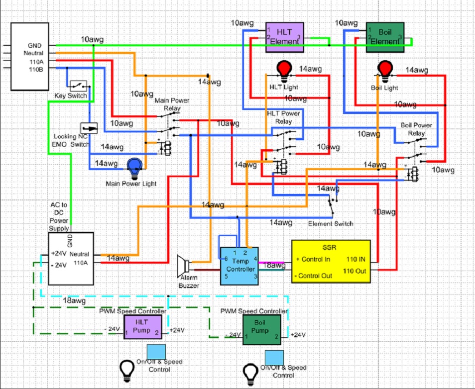
Finished up my electric brew controller. I plan on running 2 heating elements (never on at the same time). 1 in the HLT that is controlled with the temp probe + PID and 1 in the Boil Kettle that is controlled with the PID manually. Each element is on an outlet plug. Each 24V Pump is also on a plug after the PWM. The temp probe is also on a plug (I figure I could always plug a different one in to see temps in the boil kettle [even if it wasn't as accurate] to monitor cool down.)
I also figure if I ever wanted to, I could add a second PID and SSR easily enough when I goto HERMS. (I found some nice 90amp SSR for free)
Everything look wired correctly? (Not shown is a 1 amp fuse inline on the power to my PID.)

Thanks
Brew.jpg
 
Schematic looks okay to me. You will have to remember to switch the PID over to manual mode when you go from HLT to Boil. And the temp display will be for the HLT even when you are on Boil. For an extra $30 now (since the SSR are free) you could have a separate PID for the boil and not have to worry about reprogramming the PID. This would require a slight change in your wiring, though.
 
Been going back and forth with adding the 2nd PID. Would have to cut 3 more holes in the panel (PID, SSR & Temp probe connection). Then I could piggy back off the power and neutral from one PID to power the new PID, un-chain the incoming power on the relay's from the SSR and power each from each separate SSR. Chain the input to the SSR's so they both have incoming power (safe since both will never be on at same time with my on-off-on selector switch). I would leave the alarm and only have it hooked to the HLT. Run new control wires to New SRR and done! Also been debating a toggle switch to shut off power to the alarm.
Why do a lot of diagrams have toggle switches for each PID power? Why not have them on all the time? Since the output is controlled? (re-looked and answered my own question: P-J usually doesn't include a main power switch, so my main power switch replaces his PID power toggles, I think)
Why do all of P-J's diagrams show no breakers with 1 PID but breakers feeding each element coil on 2 PID systems? If they can never be on at the same time like I have them wired? (again P-J's usually allow both to be on in those diagrams so would draw more amps than my set up with the on-off-on switch.)
 
Been going back and forth with adding the 2nd PID. Would have to cut 3 more holes in the panel (PID, SSR & Temp probe connection). Then I could piggy back off the power and neutral from one PID to power the new PID, un-chain the incoming power on the relay's from the SSR and power each from each separate SSR. Chain the input to the SSR's so they both have incoming power (safe since both will never be on at same time with my on-off-on selector switch). I would leave the alarm and only have it hooked to the HLT. Run new control wires to New SRR and done! Also been debating a toggle switch to shut off power to the alarm.
Sounds correct.

Why do a lot of diagrams have toggle switches for each PID power? Why not have them on all the time? Since the output is controlled? (re-looked and answered my own question: P-J usually doesn't include a main power switch, so my main power switch replaces his PID power toggles, I think)
It's a personal preference thing. My designs usually have the main power switch control power to the PID('s), so they are on whenever the panel is energized. The PID displays then act as a main power on indicator. The PID's use so little power, there is no reason not to have then on whenever the panel is "live."

Why do all of P-J's diagrams show no breakers with 1 PID but breakers feeding each element coil on 2 PID systems? If they can never be on at the same time like I have them wired? (again P-J's usually allow both to be on in those diagrams so would draw more amps than my set up with the on-off-on switch.)
If both can be on at the same time, then you need a 50+ A main breaker on the panel power feed which requires 6 AWG wire. By putting 30 A breakers in for each element circuit, you can then use 10 AWG wiring after the breakers, which is cheaper and a lot easier to work with (more flexible.)

Brew on :mug:

So I may have skipped that step. I have 6 AWG all the way up to my panel because I have a 50 amp spa gfci breaker. In my panel I have 10 AWG inside because only 1 element can be on at a time. My thinking was 1 element should draw less than 25 amps so I can use 10 AWG.
But if I am now thinking correctly, because I have the 50 amp breaker I should add a 30 amp breaker inside before my main power relay. Run 6 AWG wire to it from the "power in" connection and then I can use 10 AWG out from it to connect to my power relay as drawn.
Reading P-J's wire diagrams he always states that the 25-30 amp breakers must reside inside the control panel. I have some that the actual switch would reside outside but the body would be inside. Think that is ok?

OR buy a 30amp GFCI and swap out my 50amp one which might be a lot easier. But more expensive.

Yes, the breaker handle can be outside of the panel enclosure, as long as the breaker body is inside the panel.
 
Back
Top