What does PCB arcing look like?

Homebrew Talk - Beer, Wine, Mead, & Cider Brewing Discussion Forum

Help Support Homebrew Talk - Beer, Wine, Mead, & Cider Brewing Discussion Forum:

This site may earn a commission from merchant affiliate links, including eBay, Amazon, and others.

rocketman768

Supporting Member
HBT Supporter
Joined
Feb 5, 2008
Messages
1,083
Reaction score
28
Location
Evanston, IL
Guys,

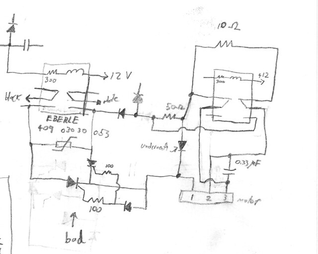
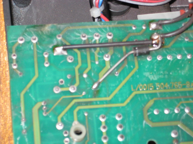
I picked up a centrifuge that had been discarded since it was blowing fuses. I have spent the last few days reverse engineering the schematic, but as I look at the under side of the PCB, I can see white marks on the surface connecting some of the solder points and traces. Is this evidence of arcing?

I am wondering, because the white arcs are only on the high-voltage AC components like the transformer, motor relays, etc, and because the white marks have a very distinctive and consistent curvature to them. Also, there is A LOT of iron dust inside the centrifuge (from the wearing-down of the motor brushes and commutator I presume) including on the PCB and the piece of plastic that the PCB was resting on (so much dust that my hands are black after working on this thing), so that makes me suspicious of arcing also.

I only have 2 more fuses to blow for this thing, so before I just clean the hell out of everything and hook it up again, I wanted to see if anyone could tell me if this is arcing or not. Thanks!

5564299681_dc02b48734_z.jpg
 
It looks like the board has been wet and powered up at the same time, as shown by the white solder oxidation residue. Look for additional deposits and a "Tide" line in the case to confirm this. Use a little bit of tooth paste and a throw away tooth brush to clean up the solder residue from the board, then rinse with isopropyl alcohol before powering up again. If there are other devices with enclosures like relays on the board, you need to pop the covers and see if things are still okay underneath.
 
I wouldn't think that this would be an indication of arcing. In my experiences, arching is characterized by black deposits at the area of contact. My initial thoughts on why you are having fuses blow would be that motor itself. With the amount of iron deposits you're finding in the case, I would at a minimum blow the motor out with compressed air. If the coils are shorting on the motor you'll have a decrease in the motor power and an increase in amperage, thus the blowing of the fuses. If you continue to have problems, check the current through the system. Also, how large are the fuses?
 
No, not arcing. I can't see it clearly, but it's probably tin whisker growth from lead-free solder. Pretty common problem since the intro of RoHS standards in PCB manufacturing.

I don't know too much about it (i.e., how to get rid of it for good) since I haven't had a problem with it. But I do believe the white stuff can be conductive, and may be causing the fuses to blow. Just clean it off and try again. You could take some spray urethane or similar and conformal coat the back of the board.
 
I wouldn't think that this would be an indication of arcing. In my experiences, arching is characterized by black deposits at the area of contact. My initial thoughts on why you are having fuses blow would be that motor itself. With the amount of iron deposits you're finding in the case, I would at a minimum blow the motor out with compressed air. If the coils are shorting on the motor you'll have a decrease in the motor power and an increase in amperage, thus the blowing of the fuses. If you continue to have problems, check the current through the system. Also, how large are the fuses?

It's not the motor. It still blows the fuse when the motor is disconnected from the board. The fuse is 4A @ 250V. The device works until the lid switch closes, so I have been tracing backwards from the lid switch (which closes one of a pair of relays that give power to the motor and some regulators and such).
 
It looks like the board has been wet and powered up at the same time, as shown by the white solder oxidation residue. Look for additional deposits and a "Tide" line in the case to confirm this. Use a little bit of tooth paste and a throw away tooth brush to clean up the solder residue from the board, then rinse with isopropyl alcohol before powering up again. If there are other devices with enclosures like relays on the board, you need to pop the covers and see if things are still okay underneath.

No tide lines, just a crapload of iron dust coating everything. So this white stuff is oxidized solder? Is it conductive?
 
Looks like the lines are a result of the magnetic iron powder and water, cleaning of the deposits will clear that problem but if it is still killing a 4 amp fuse there is something else that has shorted out. My guess would be a transformer or relay that is wet, filled with iron powder, or both to get that much current flow.
 
Looks like the lines are a result of the magnetic iron powder and water, cleaning of the deposits will clear that problem but if it is still killing a 4 amp fuse there is something else that has shorted out. My guess would be a transformer or relay that is wet, filled with iron powder, or both to get that much current flow.

Hm. I just found an SCR whose anode and cathode have 0 resistance between them...
 
Hm. I just found an SCR whose anode and cathode have 0 resistance between them...

Is the SCR connected to a varistor? If it is, its function is to blow the fuse in case of an overvoltage. Take the SCR off and power up the board (fully connected to its external loads) without it. If the fuse doesn't blow, replace the SCR.

One last tip: if you're offered a replacement SCR that's not exactly the one you need, DON'T TAKE IT. SCR's and triacs are notorious for their sensitivity to noise on the gate. I had an electronic typewriter a few years ago, that drove me crazy for almost 2 weeks, until I finally figured the brand new replacement triac I had bought was getting triggered by gate noise, and driving the regulator crazy.

It is indeed connected across a varistor. I'll desolder it and see what happens.
 
Let us know how it goes.
That setup is known as a "crow bar", and it's meant to protect sensitive electronics from power supply overvoltage, by quickly blowing the fuse if it occurs. That means, be careful not to use the device without that protection, or you can fry your electronics. Also check the varistor. It's resistance should be very high (most multimeters will show infinite) without voltage, and should drop sharply when voltage exceeds its rating. Either way, if you have the high resistance without voltage, you're ok. You don't need to do the high voltage test. If you want to do it anyways, put a resistor in series with the varistor, to allow just a few milliamps to go through. The voltage over the varistor will drop to almost "0" when you go over its voltage rating.

That was it! Working great now.

Here is the relevant part of the schematic and the offending SCR

5565766580_945b689716_z.jpg


What was going on was that the SCR had gone bad and its anode and cathode were somehow internally shorted, causing a short circuit from neutral to hot and blowing the fuse.
 
Hmmm...I'm having a hard time figuring that circuit. Must be getting rustier than I thought. :(
Anyways, I'm glad you could fix it.:rockin:
 
Back
Top