
Two panel set up
Separate high voltage panel.
I am working on a new setup and trying to come up with a drawing. I want to have 4 three way selector switches that switch from manual to auto(raspberry pi) and off for the elements and two pumps.
I also need to figure out an automatic valve with a float switch for filling the hlt in the morning.
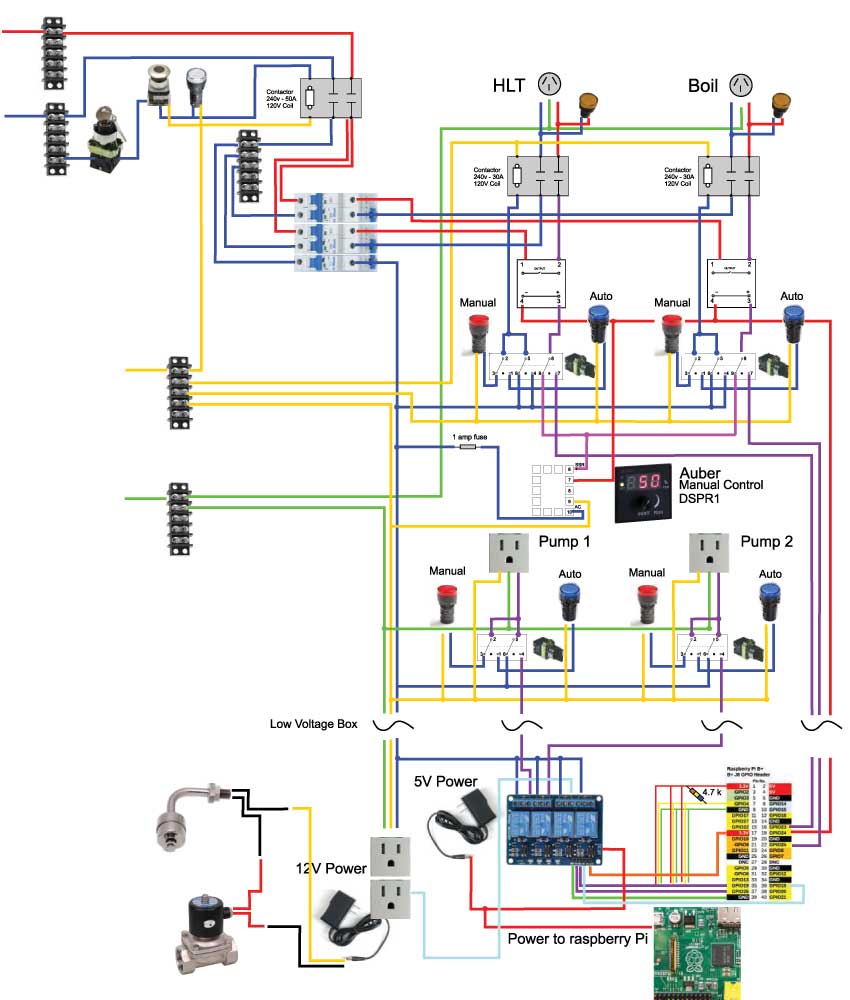
Right now I'm working on the high voltage box. I have this drawing that I came up with but wanted the experts to let me know where I've gone wrong, if at all. It might look similar to PJ's but don't be fooled, I designed this mess and don't want anybody else to run with this until the experts chime in.
I have a keyed switch then an e-stop going to a 50 amp contactor which leads to one 15 amp and two 25 amp breakers. The 15 amp breaker runs the indicator lights, contactors, two pumps and runs to the low voltage box. In the high voltage box I will have an Auber dial boil control that is hooked to each of the ssr's in the manual mode. In the "auto mode", the raspberry pi will drive the ssr's. Similarly, the pumps will turn "on" in the manual mode and be controlled with a Sain-smart 4 channel relay and the raspberry pi.
Other components like the float switch, valves and temp probes will all be hooked up to the low voltage box and any connections to the high voltage box will be maid with a xlr plug.
My thoughts with separating the boxes is so that if anything happens to the pi, I can still run it with just the high voltage box and also to just separate those components.
Separate high voltage panel.
I am working on a new setup and trying to come up with a drawing. I want to have 4 three way selector switches that switch from manual to auto(raspberry pi) and off for the elements and two pumps.
I also need to figure out an automatic valve with a float switch for filling the hlt in the morning.
Right now I'm working on the high voltage box. I have this drawing that I came up with but wanted the experts to let me know where I've gone wrong, if at all. It might look similar to PJ's but don't be fooled, I designed this mess and don't want anybody else to run with this until the experts chime in.
I have a keyed switch then an e-stop going to a 50 amp contactor which leads to one 15 amp and two 25 amp breakers. The 15 amp breaker runs the indicator lights, contactors, two pumps and runs to the low voltage box. In the high voltage box I will have an Auber dial boil control that is hooked to each of the ssr's in the manual mode. In the "auto mode", the raspberry pi will drive the ssr's. Similarly, the pumps will turn "on" in the manual mode and be controlled with a Sain-smart 4 channel relay and the raspberry pi.
Other components like the float switch, valves and temp probes will all be hooked up to the low voltage box and any connections to the high voltage box will be maid with a xlr plug.
My thoughts with separating the boxes is so that if anything happens to the pi, I can still run it with just the high voltage box and also to just separate those components.


