
vinylicious
Well-Known Member
Well, its time to jump into the pool:rockin:
I am looking to make the jump from extract to all-grain. At the same time, I want to make the jump from using propane in the driveway to indoor electric brewing in the basement. This summer has been brutally hot, and I don't need to mention the "unpleasant winters in Buffalo, NY.
So here is my proposed system:
Single Tier e-HERMS with 3 Keggles and 2 pumps
Bottom drain HLT with copper HERMS Coil
Bottom Drain MLT with Jaybird false bottom
BK (existing keggle used for extract batches) with dip tube
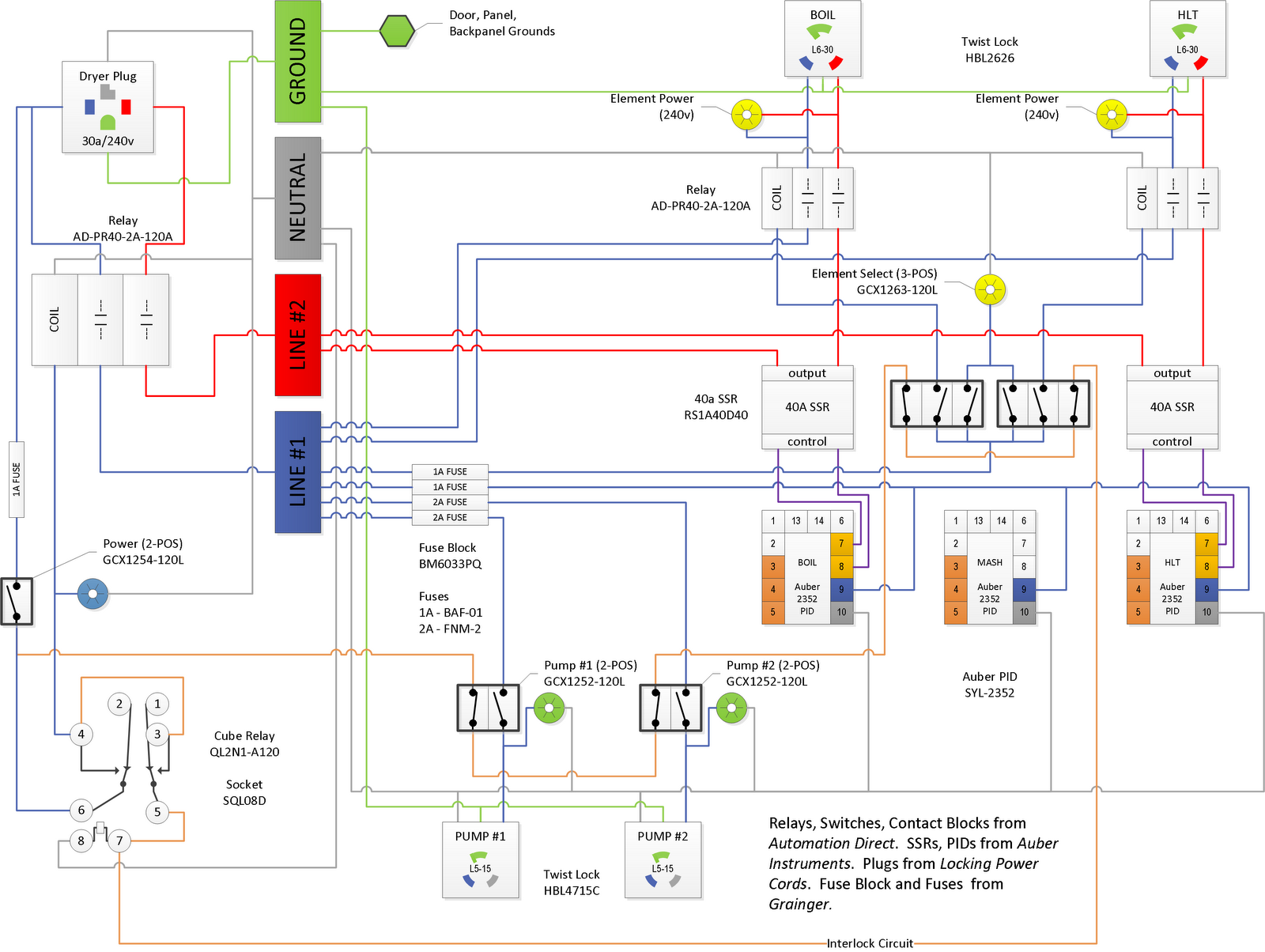
Basically, I want to build a panel similar to Bolts build (found here), with a few small modifications. I would like to add an Emergency Stop to the panel and I also plan on using 2-way and 3-way switches with separate LED indicator lights.
Here is my proposed layout for the control panel:

The brewery will be setup in the basement workshop. There is no 220 service now, but the main panel for the house is located on the opposite wall of where the brewery will go and has an old 40a breaker that is no longer in use. So the plan is to replace the old 40a breaker with a 30a GFCI breaker right in the panel and wire up a 220 outlet on the other side of the room. I have started to acquire some of the parts and will update with as many photos as possible. I always appreciate all the documentation on this board.
What I need is help with the electrical plan. How can I add an Emergency Stop into this diagram?
I am looking to make the jump from extract to all-grain. At the same time, I want to make the jump from using propane in the driveway to indoor electric brewing in the basement. This summer has been brutally hot, and I don't need to mention the "unpleasant winters in Buffalo, NY.
So here is my proposed system:
Single Tier e-HERMS with 3 Keggles and 2 pumps
Bottom drain HLT with copper HERMS Coil
Bottom Drain MLT with Jaybird false bottom
BK (existing keggle used for extract batches) with dip tube
Basically, I want to build a panel similar to Bolts build (found here), with a few small modifications. I would like to add an Emergency Stop to the panel and I also plan on using 2-way and 3-way switches with separate LED indicator lights.
Here is my proposed layout for the control panel:
The brewery will be setup in the basement workshop. There is no 220 service now, but the main panel for the house is located on the opposite wall of where the brewery will go and has an old 40a breaker that is no longer in use. So the plan is to replace the old 40a breaker with a 30a GFCI breaker right in the panel and wire up a 220 outlet on the other side of the room. I have started to acquire some of the parts and will update with as many photos as possible. I always appreciate all the documentation on this board.
What I need is help with the electrical plan. How can I add an Emergency Stop into this diagram?

