summerofgeorge
Well-Known Member
I've been thinking waaaay too much about what to use for my control panel. I just want to do it right. I'd like to stick with something LED (as opposed something along the toggle switch route). I guess I have two questions:
Switches vs Push buttons - any reason to use one over the other besides personal preference? From what I've seen, the push buttons are a little cheaper.
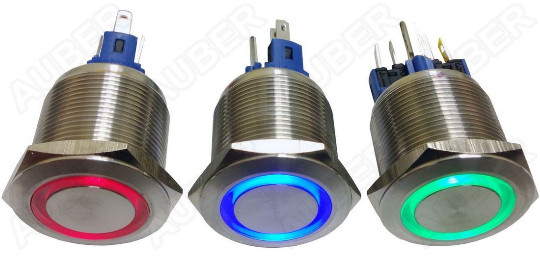
Non-illuminated switches/push buttons with separate LED light vs all in one - going separate looks like the cheapest route...all in one is better if space is an issue. Any other reason to go with one over the other?
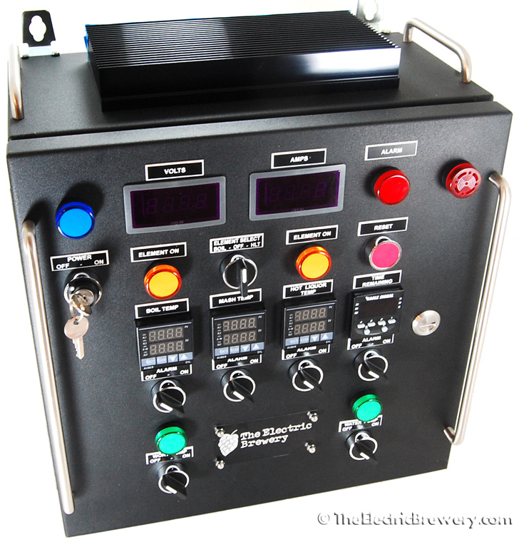
A lot of people have awesome (and different) setups and they all look really good! I just can't decide what I want.
Switches vs Push buttons - any reason to use one over the other besides personal preference? From what I've seen, the push buttons are a little cheaper.
Non-illuminated switches/push buttons with separate LED light vs all in one - going separate looks like the cheapest route...all in one is better if space is an issue. Any other reason to go with one over the other?
A lot of people have awesome (and different) setups and they all look really good! I just can't decide what I want.

")