Stc-1000+

Homebrew Talk - Beer, Wine, Mead, & Cider Brewing Discussion Forum

Help Support Homebrew Talk - Beer, Wine, Mead, & Cider Brewing Discussion Forum:

This site may earn a commission from merchant affiliate links, including eBay, Amazon, and others.
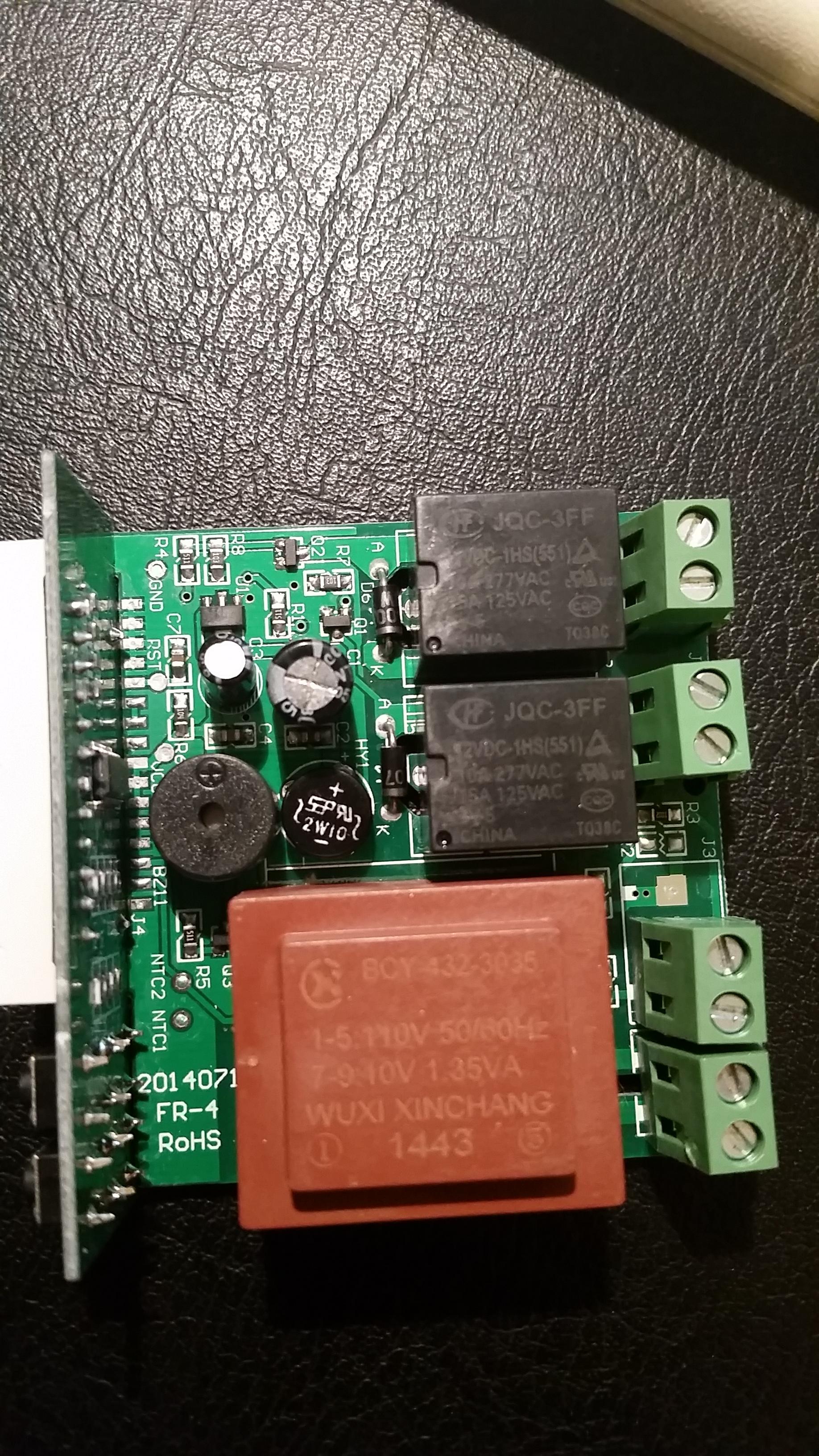
Done some real testing. Here is the setup:
Pr0.png

Here is the result:
Pr0_real.png

Datafile:
https://dl.dropboxusercontent.com/u/9236068/Pr0.txt

There is a bug in first level. As you can see the ramp of 50C is ignored. Try this twise just to make sure.

Else; Work great. With less filtering the and faster response it is perfect.

I use
hy=0.1
cd=0
hd=0
rP=0

I calibrate temp at aprox 15C (tc=+0.4C) and notised that i need anoter 0.4C when temp is higher, at aprox 70C. Maby the temp scale is not linear?

Great job Mats!!

Hi!

That curve looks ok to me. It seems it takes you pretty much exactly 20 minutes to reach 50C, so it moves on to 65C pretty much exactly by the time you get there. Which would be the correct behaviour.
And yes, the temperature-resistance curve of the NTC is very non-linear. So if you need to calibrate around your working temperature.
 
Eehh.. I thought the step counter/timer ie 50C@20min start counting when reach set temp(50C)? Have i missed something? Does the timer run even in the stepup delay?
 
Eehh.. I thought the step counter/timer ie 50C@20min start counting when reach set temp(50C)? Have i missed something? Does the timer run even in the stepup delay?

Well, I think you think of this as a 'mashing' firmware and I don't :)
To start the 'step' once the temperature is reached is pretty mashing specific behaviour. It is simply a programmable (in minutes) thermostat. The same thing goes for the PID firmware. It is not brewing specific.

Now, I could consider a brewing firmware. I am actually working on one, but it will be simpler and to my needs first. If someone else has an interest in then that is fine, but I'm not ready to share anything yet and I don't really know when I will be either.
 
Oops I`m sorry! I just thought it start counting when reach set temp. My bad. I now understand that the timer run from start to end. My setup increase 1,6C/min and I can calculate that in, no problem :)

Again sorry for calling it a bug, when it was all ok!
 
Oops I`m sorry! I just thought it start counting when reach set temp. My bad. I now understand that the timer run from start to end. My setup increase 1,6C/min and I can calculate that in, no problem :)

Again sorry for calling it a bug, when it was all ok!

No worries :)
 
Hi Mats,
I tried the firmware @ the weekend with sourdough fermentation and therefore it is perfect.
I get perfect results, here some pictures.
the fermentation box
https://www.homebrewtalk.com/attachment.php?attachmentid=249930&stc=1&d=1421696409
the sourdough
https://www.homebrewtalk.com/attachment.php?attachmentid=249931&stc=1&d=1421696409
and the baked bread
https://www.homebrewtalk.com/attachment.php?attachmentid=249932&stc=1&d=1421696409

For sourdough fermentation it´s no problem that the timer starts immediately.

Regards Gerald

IMG_20150117_183223.jpg


IMG_20150118_095159.jpg


IMG_20150118_160540.jpg
 
Hi Mats,
I tried the firmware @ the weekend with sourdough fermentation and therefore it is perfect.
I get perfect results, here some pictures.
the fermentation box
https://www.homebrewtalk.com/attachment.php?attachmentid=249930&stc=1&d=1421696409
the sourdough
https://www.homebrewtalk.com/attachment.php?attachmentid=249931&stc=1&d=1421696409
and the baked bread
https://www.homebrewtalk.com/attachment.php?attachmentid=249932&stc=1&d=1421696409

For sourdough fermentation it´s no problem that the timer starts immediately.

Regards Gerald

Well... Gotta say, that looks awesome! :)
 
Looks like there may be a new hardware version. I posted it on GitHub but I figure I would share it here as well. When I cracked my STC-1000 open to flash it the header pins were spread out across the front of the board. Looking for a labeled pin out so I can try and flash mine. I have ordered a new one to see if it is the same.
ct2o7mW.jpg
 
Looks like there may be a new hardware version. I posted it on GitHub but I figure I would share it here as well. When I cracked my STC-1000 open to flash it the header pins were spread out across the front of the board. Looking for a labeled pin out so I can try and flash mine. I have ordered a new one to see if it is the same.

This is exactly what I found tonight when I opened my STC. As I'm quite a novice to this, I was hoping to find one similar to the post on blackboxbrew but alas not the case. I have until Jan 31 to return (Amazon). So, if you find the way to work with this, great! Otherwise I will return this next week.

This has been discussed before.
Short answer is no.
 
This has been discussed before
Short answer is no.

Thanks! How do you get the correct version (if ordering from Amazon)? I could always order the one from blackboxbrew.... and I apologize in advance if that is already on this thread (its a long one, 158 pages so far!)
 
Unfortunately no guarantee when ordering on amazon, they typically don't know what they have. I have them in stock as well if you need them, but all of mine are already flashed.

Greg
 
Sorry about that, I should have read the whole thread. I am crossing my fingers on the 2 I ordered. if they don't pan out ill order one from blackboxbrew.
 
Just wanted to shout out a great big thanks to @sfish for so generously donating an extra free membership in the pointcity-homebrew christmas raffle. One that I just happend to actually win.
Thank you!
 
Just wanted to shout out a great big thanks to @sfish for so generously donating an extra free membership in the pointcity-homebrew christmas raffle. One that I just happend to actually win.
Thank you!

It could not of gone to a more worthy member, thank you for your work on this project.
 
Last edited by a moderator:
can anybody help
arduino uno on com3 windows 7 set to 115200 baud no line ending
devices manager says all is running
arduino set to right port com 3
serial monitor recognizes uploaded sketch
uploading to arduino says done ok
wiring from stc to arduino checks out on ohm meter continuity good
stc is a A400_P Version 1.1
when [I hook it up to arduino the read out comes on the stc then it goes to EE and alarm sounds
pressing send d in serial monitor produces no result
I disconnect as EE says short circuit, can't go further error somewheres
the arduino was new hooked it up,it registered on with green led, yellow flashing led under 13 pin came on I assume it signifies its working
after uploading the 1.07 sketch no flashing anymore green led for on on arduino lights up yellow led under 13 pin also lit up no flashing
I assume it means the stc sketch is loaded not the flashing led sketch
 
Connect the probe to keep the alarm from sounding (and EE displaying).
When you hook up the arduino to the stc, it might reset and leave the com port open if you have the serial monitor open. Disconnect the arduino. Close the IDE. Connect the arduino to the stc. Connect arduino to the PC again. Reopen the IDE. Make sure to select the correct port. Open serial monitor and try again.
If all wiring is good, you should be golden.
 
I finally broke down and bought a few Flashable V1 Stc1000 units from Will at BlackBoxBrew.com I think he deserves a plug for being awesome.

If you want a flashable unit, or even flashed, I totally recommend him. His prices were really good and we had a small issue where the invoice he sent me to PayPal reverted my shipping address to a property that I dozed the house to rebuild. Needless to say, it went back to him. He shipped it right back out to me as soon as he got it and it was here super fast! Thanks Will!!

Now I'm taking these bad boys to my friends house to flash. I'm going to build one into a project box for portability (and I want to use it as a sous vide controller) the other one I am going to hard wire, and install into the top plastic part, of my $50 Craig's list fermentation chamber.

image.jpg
 
Has anyone attempted to lengthen the temperature probe wire length? Splice in some additional wire and/or found a source for a longer probe that is compatible?

If so, would be interested to know the source, wire gauge used, and amount of temperature correction required.

Thanks in advance!
 
Yes, I think so.
Use whatever you have at hand. Unless you need extreme lengths it should not be a problem.
 
Has anyone attempted to lengthen the temperature probe wire length? Splice in some additional wire and/or found a source for a longer probe that is compatible?

If so, would be interested to know the source, wire gauge used, and amount of temperature correction required.

Thanks in advance!

I see no reason you can't. Just remember the splice won't be waterproof.

I built all my temp probes for my BCS controller. There's nothing to them. It a very simple thing. The sensor increases or decreases resistance, so there's nothing complex about it.

I believe it's 22 gauge on the ones that come stock. I'd simly strip, connect, twist, solder and shrink wrap the individual wires and then shrink wrap them together.

I doubt you'll notice any difference in temp reading.
 
Has anyone attempted to lengthen the temperature probe wire length? Splice in some additional wire and/or found a source for a longer probe that is compatible?

If so, would be interested to know the source, wire gauge used, and amount of temperature correction required.

Thanks in advance!

I used a spool of speaker wire I had laying around. it worked just fine.
 
the other one I am going to hard wire, and install into the top plastic part, of my $50 Craig's list fermentation chamber.

Do you have any links on how to do this. I've been on-and-off looking for a dummies version of how to replace the thermostat on my refrigerator with an STC1000+ and avoid having a box duct taped to the side of my ferm fridge.
 
Do you have any links on how to do this. I've been on-and-off looking for a dummies version of how to replace the thermostat on my refrigerator with an STC1000+ and avoid having a box duct taped to the side of my ferm fridge.

Here is how I did my fridge conversion. You should be able to do something similar with other fridges. To find out what wires you need to connect you could unplug the fridge, take apart the temp adjuster and then use a multimeter to check continuity between the temp adjuster and the wall plug. You should just have to find hot and neutral. Then find the one that connects to the compressor. Mine happened to be red to the compressor, blue was neutral and brown was hot. I then tested my theory by connecting the hot (brown) wire to the compressor (red) wire and plugged the fridge on. The compressor kicked in and i was off to the races.

YMMV but Good luck.
 
Do you have any links on how to do this. I've been on-and-off looking for a dummies version of how to replace the thermostat on my refrigerator with an STC1000+ and avoid having a box duct taped to the side of my ferm fridge.

No, but I'm sure there is something on line.

It's not difficult. You just want to disconnect the internal thermostat and run the power to the controller. Each unit will be slightly different due to the location of the thermostat and how the wires are routed through the unit. Mine is an expensive one where everything is replaceable vs being installed through walls and insulated over...etc.

Make sure the stc can handle the amps for the chamber you're using. I believe the stc is rated for 15 amps at 120v, so shouldn't be an issue for most fridges.

*edit* there you go. I see someone got you some info above. It's not hard, so don't be intimidated. Good luck!
 
Simple question, the user manual for my stc before flashing gave range as -50 to 99degrees C . I suspect that was the case for all A400_P's.I noticed the user manual for the 1000+ states -40 C to 140 degrees C .does this remarkable firmware change, extend the range of the controller? Kind of irrelevant but seems a bonus.
 
Well, the range needs to be taken with a grain of salt. The NTC temperature-reaistance curve is very non-linear, so while you can squeeze some more range out of the ADC, accuracy gets worse the further you get from +25C.
I think the main reason they state 99 degrees in the stc manual, is that it only has 3 digits and one is used for decimal. I solve it by dropping the decimal when I need all three digits, but I guess they didn't want to mess with that.
 
Alpha:
I know that you have focused on the STC-1000+ controller, but have you seen the ITC controllers from Inkbird? Didn't know if these controllers were programmable. They are similar to the STC, but in Fahrenheit instead of Celsius. If they were programmable, would this allow for more features since I know the code is limited?

Just a thought.

Links: ITC-1000
ITC-2000
 
Last edited:
@Perzellbrewing:
Yes, I've seen them. What makes the STC-1000 (A400_P version that is) so suitable, is that it has a PIC microcontroller, so it has tools (compilers et.c.) and datasheets availiable.
I don't know anything about these controllers, it would probably be possible (as they are programmed at some point during manufacturing), but is it practically doable?
What do these offer that the STC don't? Seems like very much the same thing, except they are preprogrammed for F. I really don't have much incentive to look into those, as it will probably be a lot of work (if even doable) for little or no benefits.
If you get one, please do let me know what MCU is used. If it is something relatively open (i.e. has the needed documentation) and has better specs than the PIC16F1828, then it might be interesting.
 
I'm trying to build a arduino pro mini set up like alphaomega and flomaster did (post 1532?). I ordered off ebay from china and of course got a few components that look a bit different than what I was expecting. I think it will still work but I'm struggling with aligning the usb to arduino as the pins aren't in the same position or have same labels. Tried a few google searches but since it is a "no name unit" I can't find anything.

Any advice would be appreciated. I've attached an image of the two components. I think it came out clear enough.

If these are totally wrong/incompatible I'll probably just scrap it. Was looking for an easier way to be able to flash update my controller. But I can open my box I suppose if and when I need to.

Thanks!
Brian

20150130_145128.jpg
 
I'm trying to build a arduino pro mini set up like alphaomega and flomaster did (post 1532?). I ordered off ebay from china and of course got a few components that look a bit different than what I was expecting. I think it will still work but I'm struggling with aligning the usb to arduino as the pins aren't in the same position or have same labels. Tried a few google searches but since it is a "no name unit" I can't find anything.

Any advice would be appreciated. I've attached an image of the two components. I think it came out clear enough.

If these are totally wrong/incompatible I'll probably just scrap it. Was looking for an easier way to be able to flash update my controller. But I can open my box I suppose if and when I need to.

Thanks!
Brian

I think you will need to remove the pin labeled 'cts', other than that, it looks like the pins you need line up fine (dtr-dtr, txd-rxd, rxd-txd, vcc-5v and gnd-gnd). But before you do anything permanent see if you can test if it will work. You can for example bend just the cts pin straight, plug in the usb and fire up arduino ide. Make sure you find the com port, if you do, you can try to upload a sketch by simply attaching the arduino to the pins and press slightly to make the connection. If you can upload like this, you are good to go. Remove the pin and solder it up.

Edit: By press slightly, I mean that your arduino will be pointing up (vertically), put some pressure on the top of it (horisontally) so that it wants to bend against the pins. This way you will have a good connection (I've done this myself a couple of times to upload a sketch without having to solder in the connector on the arduino).
 
Back
Top