Stc-1000+

Homebrew Talk - Beer, Wine, Mead, & Cider Brewing Discussion Forum

Help Support Homebrew Talk - Beer, Wine, Mead, & Cider Brewing Discussion Forum:

This site may earn a commission from merchant affiliate links, including eBay, Amazon, and others.
Alpha, I'm scouring the thread to pull together the bits of new commands and functionality that differ from the published GitHub instructional readme; The "rp", "b", "g", up/down/both display, etc. What I don't see is a cancel--would you simply go into SET menu and choose 'rn' and then 'th' to cancel a Pr# currently underway?

By the way, the latest flash is fabulous and goes without a hitch; I still want to test flashing program with/without data to preserve profiles. Plus my temp datalogger is giving me fits right now so profile testing for me is at a standstill.

But this is truly something you should be uber-proud of, it's an amazing hack!
 
Hi!
Yeah I think you are right, that are probably the main differences. And yes, that will effectively stop/cancel the running profile.
I am currently working on a better user manual (PDF) that I hope will be complete enough. I am working on storing version in User ID location at the same time, and making the sketch a little user friendlier.

And thanks for the kind words! It is really nice to have some positive feedback as well (not that I don't appreciate bug reports and opinions and such also)!
I do think it is coming along nicely :)
 
I think the sketch is about as user-friendly as it gets--
-open in IDE (if IDE complains about wanting to make a folder, let it)
-check compile
-upload
-hook up STC
-open monitor Ctrl-Shift-M
-change baud
-send 'd' to verify
-send 'f' or 'g' to flash all or program only
-listen to the STC make noise for 20s

Yeah, and I won't change that I'll just add some helpful output, like a greeting when you connect (and urge you to connect wires and send 'd') + some more info on d command if a previous stc-1000+ firmware is found and what version it is and what version sketch holds and the options for flashing. Maybe I can even come up with something to indicate if EEPROM format has changed.
So, just some assistance basically.
 
Are you letting all of the ladies know that you've reflashed your temp controller and want to put it in their fermentation chamber? If that doesn't do it, nothing will.
 
Are you letting all of the ladies know that you've reflashed your temp controller and want to put it in their fermentation chamber? If that doesn't do it, nothing will.

Hope he's not using yeast to ferment that.


Oh god, I just went too far. My sincere apologies.
 
My two new STC-1000's came in today - I only opened one of them up - but it was a flashable unit! :rockin: I think I'll try and flash it without soldering the pin header on - just to see if its possible...

EDIT - It wasnt possible after a couple of beers...
 
I'm really curious to see if the header-pin-holding-after-3-homebrews method really works.

Because I know from experience that soldering to the reasonably large pads was not terribly easy after 3 homebrews!
 
I just ordered a couple STC's from AGPtek since everyone seems to be getting the programmable ones from there. I already have two running separate chest freezers but they're installed rather well at this point, so I'd rather play with something new before I tear those apart.

I also have an Uno on the way, all of which is expected tomorrow.

Been watching this thread from the beginning and have been rather impressed with what I'm seeing!

Alpha, when do you expect to have an updated install guide up? As soon as you do, I'll gladly follow it and let you know the results.
I'm completely new to anything Arduino, but have been in IT for almost ten years now, so I don't expect it to be too hard for me.

I saw way back in the thread a post about soldering a 5 pin header on the stc. Does anyone have a source for the parts to do this?
 
Has anyone attempted to install a 5-pin USB jack into their project, for easy flashing? Or some other solution involving a standardized plug?

I see that microUSB supports 5-wire connections, so this could be ideal to make things quick, versus constantly hooking up individual wires.
 
Has anyone attempted to install a 5-pin USB jack into their project, for easy flashing? Or some other solution involving a standardized plug?

I see that microUSB supports 5-wire connections, so this could be ideal to make things quick, versus constantly hooking up individual wires.

It's not the same format, although there are adapter chips that would work.

I believe something like this might work in taking the place of the Arduino (Although I havent had any luck flashing with anything other than the Arduino)

http://www.oddwires.com/usb-isp-3-3v-5v-avr-programmer/?gclid=CMrC_8O5w70CFcqUfgodjLYAjg

BUT - Why bother? The firmware will become stable and the adapter will become useless. You wont have to re-flash it again. The last time I flashed mine, I didn't remove a wire - I pulled it out, popped the case open enough to get the ribbon cable in, flashed it, and had it back together in less than ten minutes.
 
Thanks, I've seen those on amazon, also. What about the ribbon cable and female connector that will mate to those pin headers?

Thats a bit tougher.... Mine came with an ISCP PIC programmer (PIC is the processor in a 1.0 STC)

http://www.ebay.com/itm/USB-PIC-Aut...706?pt=LH_DefaultDomain_0&hash=item48545cf5da

But if you dont want to buy the programmer, you could buy this cable and use either the front six pins or the back six pins, I believe it would still work.

http://www.ebay.com/itm/2-Pcs-2-54m...C-Flat-Ribbon-Cable-Length-15cm-/170941249939
 
It's not the same format, although there are adapter chips that would work.

I believe something like this might work in taking the place of the Arduino (Although I havent had any luck flashing with anything other than the Arduino)

http://www.oddwires.com/usb-isp-3-3v-5v-avr-programmer/?gclid=CMrC_8O5w70CFcqUfgodjLYAjg

BUT - Why bother? The firmware will become stable and the adapter will become useless. You wont have to re-flash it again. The last time I flashed mine, I didn't remove a wire - I pulled it out, popped the case open enough to get the ribbon cable in, flashed it, and had it back together in less than ten minutes.


I think you and I are on different pages here. I'm not talking about something to replace the Arduino. I'm talking about making it easier to flash WITH the Arduino. Currently I have wires (with tips that easily connect into the Arduino's pin slots) that are taped over individually. Each time I want to connect, I have to remove the tape from each wire, then connect them all, then hook it all up to the computer, etc.

Itd be nice if I could take a microUSB cable (5-wire) and cut off one end and have that rigged to plug into the Arduino (I only use that thing for flashing this controller --- nothing else). Then I could wire up a female end to the controller, and have it easy to hook things up to flash.


However, you make a very fair point -- at some point soon, we're gonna be 100% stable and unable to add more features. At that point, maybe more flavors will come out for different purposes. I for one wouldn't mind seeing the stock firmware basically being remade in order to flash the controller back to a simpler set of logic.
 
I just ordered a couple STC's from AGPtek since everyone seems to be getting the programmable ones from there. I already have two running separate chest freezers but they're installed rather well at this point, so I'd rather play with something new before I tear those apart.

I also have an Uno on the way, all of which is expected tomorrow.

Been watching this thread from the beginning and have been rather impressed with what I'm seeing!

Alpha, when do you expect to have an updated install guide up? As soon as you do, I'll gladly follow it and let you know the results.
I'm completely new to anything Arduino, but have been in IT for almost ten years now, so I don't expect it to be too hard for me.

I saw way back in the thread a post about soldering a 5 pin header on the stc. Does anyone have a source for the parts to do this?

Thanks!
It'll probably be a few more days before I have something that I can present and even then will probably have to update the manual somewhat if you guys are nice enough to give me some feedback (which I hope and believe you will).

Has anyone attempted to install a 5-pin USB jack into their project, for easy flashing? Or some other solution involving a standardized plug?

I see that microUSB supports 5-wire connections, so this could be ideal to make things quick, versus constantly hooking up individual wires.

I like the mini XLR connectors (just search ebay for 'mini XLR 5 pin'), they are great for tempsensors as well., but micro USB might work.

Sure, I feel also that the firmware is approaching stability and that there probably will be less and less updates. But, you never know if/when some bug is discovered, or someone comes up with some nifty feature. So I don't see anything wrong with having an at least somewhat accessible programming header.
 
I have pushed the new sketch to work branch.
It adds version number to user ID location when programming the STC and some help for the user (like if EEPROM data has changes since the version that is currently flashed).
There is nothing new in the actual firmware.
But if someone wants to try out the new sketch, please do.
Just one note, as this is the first time User ID locations are written, it will claim to no previous STC.-1000+ firmware is detected, even if there is. Disregard that, you can check with 'd' command after flashing and it should detect the version.
 
Regarding soldering, krazydave, I got these and soldered the ribbon ends to the easily reachable back of the STC -- note that case may or may not close on this but once I have stable firmware flashed I'm closing it up. Then I got these to use as pins from the Arduino to the connector on the ribbon cable mentioned above.

Alpha, flashing "help" is VERY NICE!
BEFORE:
STC-1000+ firmware sketch.
Copyright 2014 Mats Staffansson

Send 'd' to check for STC-1000
Enter low voltage programming mode
Leaving programming mode
Device ID is: 0x27C5
STC-1000 detected.
No previous STC-1000+ firmware detected.
Consider initializing EEPROM when flashing.
Sketch has version 0.11

Send 'a' to upload Celsius version and initialize EEPROM data.
Send 'b' to upload Celsius version (program memory only).
Send 'f' to upload Fahrenheit version and initialize EEPROM data.
Send 'g' to upload Fahrenheit version (program memory only).


AFTER:
Device ID is: 0x27C5
STC-1000 detected.
STC-1000+ Fahrenheit firmware with version 0.11 detected.
Sketch has version 0.11

Send 'a' to upload Celsius version and initialize EEPROM data.
Send 'b' to upload Celsius version (program memory only).
Send 'f' to upload Fahrenheit version and initialize EEPROM data.
Send 'g' to upload Fahrenheit version (program memory only).
 
I have a couple old PC wiring harnesses laying around. Is there any reason I couldn't use one of the four wire connectors to solder in a permanent header to both the STC and the Arduino? That way you just clip it in if you need to flash. And, no cost.


Sent from my iPhone using Home Brew
 
I have a couple old PC wiring harnesses laying around. Is there any reason I couldn't use one of the four wire connectors to solder in a permanent header to both the STC and the Arduino? That way you just clip it in if you need to flash. And, no cost.


Sent from my iPhone using Home Brew

One reason might be that you need 5 wires. You could get by with 4 if you allow target to supply power (i.e. skip 5v line and instead have STC-1000 provide power from mains), but you'll have to decide yourself if you are willing to do that (personally I would want to avoid it).
 
I was thinking it needed 3 wires, I think I got this project confused with another one. So as long as I can find a minimum 5 pin wiring harness I should be good.


Sent from my iPhone using Home Brew
 
I was thinking it needed 3 wires, I think I got this project confused with another one. So as long as I can find a minimum 5 pin wiring harness I should be good.


Sent from my iPhone using Home Brew

A USB cable would work, 4 wires, plus the shield at ground.
 
The ramp test is going beautifully and I have been running through shorter scenarios with a second unit. Haven't found any problems.

The only thing I might recommend, is for users to remember how the ramp function works (segments the step out into 8 even temperature changes). If you want a smoother transition over a long period of time, spread it across more than one step.

The last step in my test (not quite completed yet) is a 48 hour ramp from 68F to 33F. That gives me 4.375*F steps. If I were actually crashing something that I wanted a really smooth transition for, I would spread it across two steps and have 16 ramp changes (and 2.1875*F changes in this case, well it would round that to the tenth).

Just something to bear in mind.

Alpha, this thing is pretty awesome.

RampTest.jpg
 
The ramp test is going beautifully and I have been running through shorter scenarios with a second unit. Haven't found any problems.

The only thing I might recommend, is for users to remember how the ramp function works (segments the step out into 8 even temperature changes). If you want a smoother transition over a long period of time, spread it across more than one step.

The last step in my test (not quite completed yet) is a 48 hour ramp from 68F to 33F. That gives me 4.375*F steps. If I were actually crashing something that I wanted a really smooth transition for, I would spread it across two steps and have 16 ramp changes (and 2.1875*F changes in this case, well it would round that to the tenth).

Just something to bear in mind.

Disney, that is awesome! Great work! And great news!
I will try to be as clear as possible in the new user guide how ramping works, and its limitations and also suggest ramping over several steps if needed.

disney7 said:
Alpha, this thing is pretty awesome.

Ah, thanks man! That means a lot!
I truly hope somebody (besides myself) will find this firmware usable. And if I can just complete the user guide I'm thinking it is v1.0 time :)
 
I just flashed this onto my STC-1000 without any issue and am looking forward to putting it to use! FYI, I have no background in programming and had never used an Arduino prior to this, so the instructions have passed the idiot-test :)

Many thanks to Alpha, Disney and the rest of the developers collaborating on this effort! Awesome work.
 
Don't give me any credit, I'm just a mooch that has been testing and trying to poke holes in the thing.

I like your style Disney. As a European, we kind of have this notion of the typical American that is... well... let's say, not entirely positive. It is nice to know this is not true.
Though, I think you've earned your fair slice of the kudos pie. You have been extremely helpful! You and the other early adopters also deserve my thanks for daring to risk your controllers. Without you and your feedback I don't think the project would be where it is now. So, thanks!
 
Wilconrad, that is kewel! Atoughram mentioned wanting to do this; I was too worried about solder pad height diffs to try.
 
Don't give me any credit, I'm just a mooch that has been testing and trying to poke holes in the thing.

disney7, your testing/feedback has been awsomely helpful -- I am mostly hella-envious of the temp datalogging (BrewPi envy)
 
Wilconrad, that is kewel! Atoughram mentioned wanting to do this; I was too worried about solder pad height diffs to try.

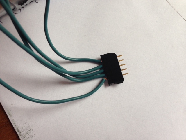
I was a bit worried about the solder pad height issue as well, but I laid the pin header on it's side and pressed it against the contacts (like below); the pins will flex enough to take up any variation in the pad height. (also, the pads were pretty consistent in height, which helps).

Flash.JPG
 
I was a bit worried about the solder pad height issue as well, but I laid the pin header on it's side and pressed it against the contacts (like below); the pins will flex enough to take up any variation in the pad height. (also, the pads were pretty consistent in height, which helps).

wilconrad, would you mind if I 'steal' your picture to include in the user guide?
Edit: I'll credit you of course...
 
I have pushed a half-done copy of the user manual to the work branch (PDF format).
I'd very much appreciate any comments/corrections on the work on it so far.
English not being my native language, strange wordings etc. Basically, anything you think will improve it.
 
I have pushed a half-done copy of the user manual to the work branch (PDF format).
I'd very much appreciate any comments/corrections on the work on it so far.
English not being my native language, strange wordings etc. Basically, anything you think will improve it.

Looks great, Mats! I think your English is better than mine! :)
 
Has anyone started documenting this project? I've started on a operation and instruction manual but I dont want to duplicate the labor.

EDIT - Nevermind - I see there has been work on it! Thank You Alpha!
 
I have pushed a half-done copy of the user manual to the work branch (PDF format).
I'd very much appreciate any comments/corrections on the work on it so far.
English not being my native language, strange wordings etc. Basically, anything you think will improve it.

I look forward to reading it through. The instructions so far have been excellent. I had no issues with anything including getting and setting Arduino first time ever for flash. It really has been a very easy process.

EDIT: Alpha, PM'd you a couple VERY minor points. You really have done a SUPER job on this project!
 
I've been following this from a few days in, and I've been amazing at the progress - kudos to alphaomega for pulling something like this off! I'll be happy to supplement the field data as soon as I get some header pins for an arduino.

One quick question tho - if the thermistor lookup table is contained in the code on github, could it be exchanged with an appropriately formatted table for any other thermistor of 'type NTC (10K / 3435)'?

For instance, from vishay (where alphaomega pulled a 10k NTC thermistor table from as reference), there is this immersion sensor, which would be really cool to use for a RIMS temp sensor - may as well use both of alphaomega's awesome DIY projects together!
 
Back
Top