Jonathan_Marino
Active Member
- Joined
- Sep 14, 2013
- Messages
- 26
- Reaction score
- 14
Hey All 
I just finished setting up a dual-mode temperature controller for my fermentation fridge.
Along the way I took a number of pictures, and hope to explain here in detail how to do this easily and with little expense.
First off, do not be afraid of the wiring! A ways back, I spent a couple years working assistant to an residential electrician, and I understand that electricity and wire diagrams can be daunting. This project is super simple, and more importantly - CHEAP!
OK, here we go!
These are the tools that I used. there are many ways to accomplish the specific tasks needed, and I will expect that if you do not own any of the equipment here, you can improvise. you are homebrewers, right?

1 - Drill
2 - Female end of extension cord (Cooler)
3 - Female end of extension cord (Heat source)
4 - Male end of extension cord (Power for unit)
5 - Colored electrical tape
6 - STC - 1000 Temp controller
7 - STC - 1000 Temp sensor
8 - Zip ties
9 - Plastic project box
10 - Wire stripper
11 - Mini hacksaw
12 - 3/8 inch spade bit
13 - 1/2 inch spade bit
14 - small phillips head
15 - utility knife
16 - wire cutter
17 - Twist Wire connectors not pictured here
Step 1 - Prepare housing setup


We will need:
black project box - for housing
2 drill bits - for drilling holes for wires
hacksaw for cutting space for STC-1000 unit
Drill 4 holes in total:

3 holes for male/female cords(will connect to heater,cooler and power outlet)
1 hole for the temp sensor(smaller hole on bottom)

Now we can punch out a hole for the unit itself.
Here I used a drill bit to punch a hole in the center, then used to hack saw to trim around until I had enough space for the unit to fit snugly. The display is larger than the back of the unit and those dimensions should not be used. Use the dimensions from the back of the unit.


Alright, step one done - so far so good, right?
Step 2 - Set up Wiring
OK, here is the part that everybody gets worried about. But I'll take it slow, and it will be easy.
First you need to make sure you have the proper wires for this particular set up. I used some old 3 prong extension cords, which work perfectly.
Here in the US the color codes for our wires are:
Black - Live
White - Neutral
Green - Ground(Earth)
In the diagram below the colors are as follows:
Brown - Live
Blue - Neutral
Green - Ground(Earth)
Male end:
Cut enough wire for the unit itself to reach an outlet. This will be the only power outlet you will need.
2 Female ends:
Cut enough wire so that the cords from your heating and cooling devices can reach these female ends.
Also, cut a few pieces of separate wire(found from discarded extension cords) About 6 inches or so

You will need 3 pieces of live(black) and 1 piece of neutral(white)
I cut extra black pieces because I zoned out and forgot I only needed 3.
OK, so at this point you should have a total of 13 wires to strip
4 pieces of loose wire: (both ends of these are stripped)
3 Live(black)
1 Neutral(white)
and 9 coming from your extension cords, 3 Live, 3 Neutral, 3 Ground.
Strip all of these wires carefully. About 1 inch of exposed wire. (some of these will be trimmed later)
Step 3 - Wiring the unit
OK, so now you have all of your wiring prepped, and we are ready to wire the device.
Here is a diagram that shows the wiring structure:

What you will do first is wire the loose pieces that we prepped earlier (3 live, 1 neutral)

Note: Any exposed wiring being placed into the back of the unit should be trimmed to a 1/2 inch.
Using a small flat-head screwdriver, turn the small screws above each slot counter-clockwise all the way. This opens the slot so that exposed wiring can enter.
After a wire is placed fully into the slot. Tighten the slot back up.
You can slide the 3 loose black wires into slots 1, 5 and 7.
You can slide the loose white wire into slot 2.

OK, next part is super easy.
The 2-pronged temp sensor can be placed into slot 3 and 4. Left/Right does not matter.
Take Live(black) wire from your heating extension cord and wire into slot 6
Take Live(black) wire from your cooling extension cord and wire into slot 8
Note: The diagram has heating and cooling backwards. My directions are correct.
OK, at this point all of the slots are occupied with the correct wires.
Now we simply connect all of the remaining exposed wires by color.
You should have 4 black wires, 4 white wires and 3 green wires left.
Here I used twist wire connectors. You can also solder these together.

At this point the device should be fully functional. But we have a few additional steps left to go.
Step 4 - Finishing touches
Use zip ties to secure all wires into place. Place them snugly behind the back wall. This will prevent any accidental slip out of the wires from there connectors. I also used a bit a electrical tape just below the twist caps to keep the wires as snug as possible.
Screw the top plate back onto the project box and admire your work. I added some striping to one of the extension cords so that there is no confusion later.


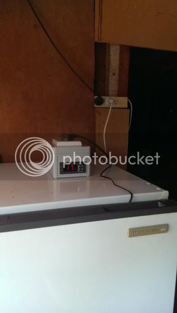
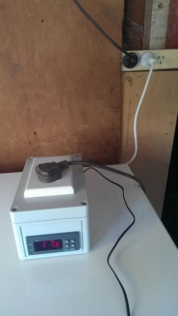
I then added couple thick pieces of velcro to the unit. this is how I am attaching to wall.

Then plugging the unit in is simple. The male goes to a house outlet. And plug your cooler and heating device to the corresponding females.

I hope this tutorial has helped. Please feel free to message me with any questions about the project or suggestions that I could add to this thread.
Thanks and happy brewing!
Jonathan
I just finished setting up a dual-mode temperature controller for my fermentation fridge.
Along the way I took a number of pictures, and hope to explain here in detail how to do this easily and with little expense.
First off, do not be afraid of the wiring! A ways back, I spent a couple years working assistant to an residential electrician, and I understand that electricity and wire diagrams can be daunting. This project is super simple, and more importantly - CHEAP!
OK, here we go!
These are the tools that I used. there are many ways to accomplish the specific tasks needed, and I will expect that if you do not own any of the equipment here, you can improvise. you are homebrewers, right?
1 - Drill
2 - Female end of extension cord (Cooler)
3 - Female end of extension cord (Heat source)
4 - Male end of extension cord (Power for unit)
5 - Colored electrical tape
6 - STC - 1000 Temp controller
7 - STC - 1000 Temp sensor
8 - Zip ties
9 - Plastic project box
10 - Wire stripper
11 - Mini hacksaw
12 - 3/8 inch spade bit
13 - 1/2 inch spade bit
14 - small phillips head
15 - utility knife
16 - wire cutter
17 - Twist Wire connectors not pictured here
Step 1 - Prepare housing setup
We will need:
black project box - for housing
2 drill bits - for drilling holes for wires
hacksaw for cutting space for STC-1000 unit
Drill 4 holes in total:
3 holes for male/female cords(will connect to heater,cooler and power outlet)
1 hole for the temp sensor(smaller hole on bottom)
Now we can punch out a hole for the unit itself.
Here I used a drill bit to punch a hole in the center, then used to hack saw to trim around until I had enough space for the unit to fit snugly. The display is larger than the back of the unit and those dimensions should not be used. Use the dimensions from the back of the unit.
Alright, step one done - so far so good, right?
Step 2 - Set up Wiring
OK, here is the part that everybody gets worried about. But I'll take it slow, and it will be easy.
First you need to make sure you have the proper wires for this particular set up. I used some old 3 prong extension cords, which work perfectly.
Here in the US the color codes for our wires are:
Black - Live
White - Neutral
Green - Ground(Earth)
In the diagram below the colors are as follows:
Brown - Live
Blue - Neutral
Green - Ground(Earth)
Male end:
Cut enough wire for the unit itself to reach an outlet. This will be the only power outlet you will need.
2 Female ends:
Cut enough wire so that the cords from your heating and cooling devices can reach these female ends.
Also, cut a few pieces of separate wire(found from discarded extension cords) About 6 inches or so
You will need 3 pieces of live(black) and 1 piece of neutral(white)
I cut extra black pieces because I zoned out and forgot I only needed 3.
OK, so at this point you should have a total of 13 wires to strip
4 pieces of loose wire: (both ends of these are stripped)
3 Live(black)
1 Neutral(white)
and 9 coming from your extension cords, 3 Live, 3 Neutral, 3 Ground.
Strip all of these wires carefully. About 1 inch of exposed wire. (some of these will be trimmed later)
Step 3 - Wiring the unit
OK, so now you have all of your wiring prepped, and we are ready to wire the device.
Here is a diagram that shows the wiring structure:
What you will do first is wire the loose pieces that we prepped earlier (3 live, 1 neutral)
Note: Any exposed wiring being placed into the back of the unit should be trimmed to a 1/2 inch.
Using a small flat-head screwdriver, turn the small screws above each slot counter-clockwise all the way. This opens the slot so that exposed wiring can enter.
After a wire is placed fully into the slot. Tighten the slot back up.
You can slide the 3 loose black wires into slots 1, 5 and 7.
You can slide the loose white wire into slot 2.
OK, next part is super easy.
The 2-pronged temp sensor can be placed into slot 3 and 4. Left/Right does not matter.
Take Live(black) wire from your heating extension cord and wire into slot 6
Take Live(black) wire from your cooling extension cord and wire into slot 8
Note: The diagram has heating and cooling backwards. My directions are correct.
OK, at this point all of the slots are occupied with the correct wires.
Now we simply connect all of the remaining exposed wires by color.
You should have 4 black wires, 4 white wires and 3 green wires left.
Here I used twist wire connectors. You can also solder these together.
At this point the device should be fully functional. But we have a few additional steps left to go.
Step 4 - Finishing touches
Use zip ties to secure all wires into place. Place them snugly behind the back wall. This will prevent any accidental slip out of the wires from there connectors. I also used a bit a electrical tape just below the twist caps to keep the wires as snug as possible.
Screw the top plate back onto the project box and admire your work. I added some striping to one of the extension cords so that there is no confusion later.
I then added couple thick pieces of velcro to the unit. this is how I am attaching to wall.
Then plugging the unit in is simple. The male goes to a house outlet. And plug your cooler and heating device to the corresponding females.
I hope this tutorial has helped. Please feel free to message me with any questions about the project or suggestions that I could add to this thread.
Thanks and happy brewing!
Jonathan
Last edited by a moderator:
")