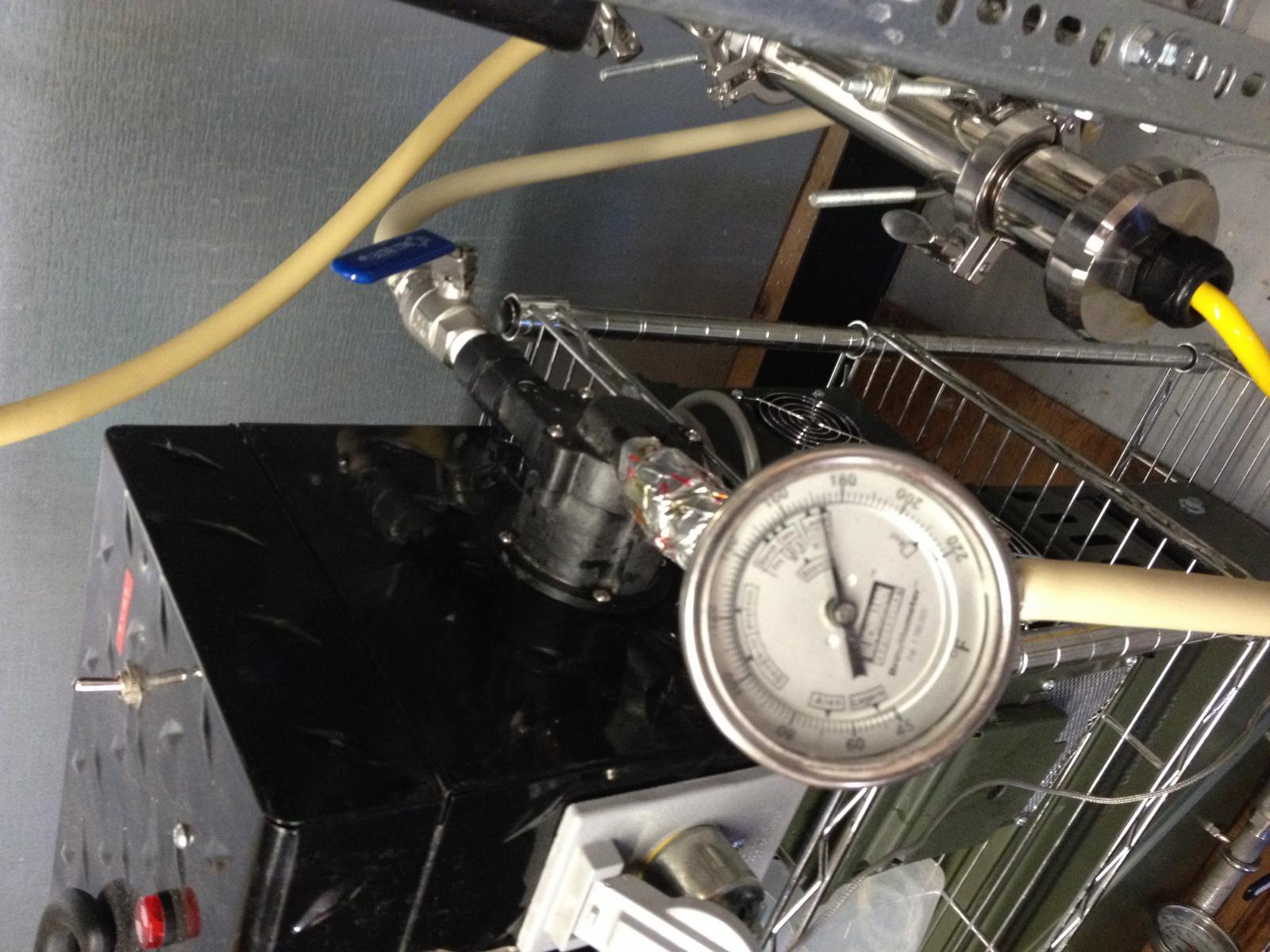
I recently built a small 600 watt 120v DIY RIMS setup and have used it a couple times for testing but now I want to add more control as well as build a nice box to house the components involved in controlling the heat and pump speed.
Here are a few of the components in the aluminum project box as well as a quick simple wiring diagram.
I'll be using a Rex C100 pid controller paired with a ssr to control the heating element. To control the pump speed I will be using a PWM circuit purchased from ebay. Inside the box will also be an ac/dc converter circuit I also purchased from ebay.
The front of the box will contain the pid display, manual override stitches for both the pump and heater as well as led indicator lights to show when the heater and pump are on.
The rear of the box will contain the 120v plug for the main power supply, a main power rocker switch and fuse. It will also have a dc barrel connector to plug in the pump as well as a standard 120 female outlet that will power the heating element. There will also be a female panel mount thermocouple jack.
Things are going to be pretty tight in the box but I think everything will fit.
I've built a few other temp controllers for other projects but they have always been low budget, simple, and were based on function over form. I'm hoping to take my time with this project and make it look nice.
I started working on a wiring diagram to help me figure out what other components I need to purchase. It's not finished but gives an idea of how everything I think everything should be wired.
Please feel free to let me know if there is something I'm missing oiut doesn't look like it would work.
I know I need to add the manual on/off switch to the heating element yet but obviously need a larger terminal block to add that.
View attachment 1421035155770.jpg
View attachment 1421035169525.jpg


