Native ESP8266 BrewPi Firmware - WiFi BrewPi, no Arduino needed!

Homebrew Talk - Beer, Wine, Mead, & Cider Brewing Discussion Forum

Help Support Homebrew Talk - Beer, Wine, Mead, & Cider Brewing Discussion Forum:

This site may earn a commission from merchant affiliate links, including eBay, Amazon, and others.
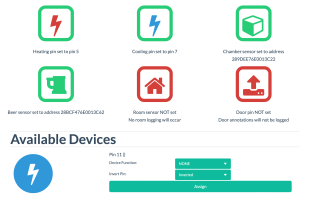
I gave up on the ESP8266 controller (Lolin D1 mini V4.0) given the ver 4 problemThorrak mentioned. I bought a ESP32-S2 and set it up no problem. Only difference I notice is with pin configuration it does not prompt for heat pin and cooling pin like the esp8266 did. I have a choice of Pin 5, 7or 11 for heat and cool. Does it matter which I use? Here are screen shots of how I have it set up. The heat and cool relays are triggered when I test it, just wondering if maybe I had a bad solder or something since pin setup looked different than the ESP8266. Thanks
 

Attachments

  • Screen Shot 2022-07-26 at 8.37.50 PM.png
    Screen Shot 2022-07-26 at 8.37.50 PM.png
    291.2 KB · Views: 0
  • Screen Shot 2022-07-26 at 8.38.07 PM.png
    Screen Shot 2022-07-26 at 8.38.07 PM.png
    242.5 KB · Views: 0
Last edited:
I gave up on the ESP8266 controller (Lolin D1 mini V4.0) given the ver 4 problemThorrak mentioned. I bought a ESP32-S2 and set it up no problem. Only difference I notice is with pin configuration it does not prompt for heat pin and cooling pin like the esp8266 did. I have a choice of Pin 5, 7or 11 for heat and cool. Does it matter which I use? Here are screen shots of how I have it set up. The heat and cool relays are triggered when I test it, just wondering if maybe I had a bad solder or something since pin setup looked different than the ESP8266. Thanks
I did the same, just could not get the V4.0 to work. I set the pins on the S2 to #5 for Heat and #7 for Cool and everything functioned as it did with the D1 (only it works now!). Many thanks to Thorrak for creating this solution!
 
I gave up on the ESP8266 controller (Lolin D1 mini V4.0) given the ver 4 problemThorrak mentioned. I bought a ESP32-S2 and set it up no problem. Only difference I notice is with pin configuration it does not prompt for heat pin and cooling pin like the esp8266 did. I have a choice of Pin 5, 7or 11 for heat and cool. Does it matter which I use? Here are screen shots of how I have it set up. The heat and cool relays are triggered when I test it, just wondering if maybe I had a bad solder or something since pin setup looked different than the ESP8266. Thanks
UHH. It's always possible that I, in my brilliance, released the firmware but forgot to add the relevant changes to Fermentrack. Let me poke at it a bit.
 
Well I'm pretty excited, after finding this project a few months ago and lurking and gathering all the materials I'm beginning the build. I ordered the ESP8266-SMD main board from Osh Park and it seems like the supply chain issues have hit the BSS138 MOSFET pretty hard. I managed to pick up a couple of the BSS138LCT-ND's just in case, will these work as an acceptable alternative? (otherwise this seems to be the next closest that's actually in stock on the market place https://www.digikey.com/en/products/detail/onsemi/BSS138K/2410031)

That said, the work put together by this community is incredible, not to mention the ongoing support for this is amazing as well. Thanks to all those who have contributed.
 
Last edited:
I can't find the BSS138LCT-ND anywhere to check specs on it, but my expectation is that you'll probably be fine. You're pushing very little current/voltage through these things, so as long as it's an N-channel mosfet in a SOT23-3 footprint you're likely good to go.
 
AH, then I'm pretty sure that I've used that exact one. I anticipate you'll be fine.
😅awesome and thank you for the help. I've got another round of soldering to do and will get that installed then. I have been finding that process somewhat enjoyable, much more so after I got things dialed in, my first resistor... Was not pretty haha
 
Does anyone have issues with relays failure prematurely? Doesn't seem like I can get 2-3 beers before they fail. Using sainsmart Amazon 5v 2ch.
 
I’ve not had a relay board fail yet - and I have a build that has been controlling my keezer for 4+ years. :(

What is the load you’re switching that is causing them to fail?
 
I’ve not had a relay board fail yet - and I have a build that has been controlling my keezer for 4+ years. :(

What is the load you’re switching that is causing them to fail?
Have a small merchandiser, should be sub 8a max and a smaller merchandiser they both have the same problem.
 
Thorrak,

Any suggestions on adjusting the cooling delay on my Fermentrack setup? I am currently using the V0.11 serial set up as I kept having problems with the Wi-Fi version, I was using a Wemos D1 mini v4, but switched them out to the v3 due to the issues you have mentioned in previous threads.

I see in the packet "TempCrontrol.h" there are parameters for delay setting, but comparing the various version (v0.11, 0.14, 0.14 low delay, etc.) they all appear to have the same settings in this portion of the code (see attached).

As mentioned I am having problems with Wi-Fi stability so I am using serial ports which at least let the program run.

Appreciate any feedback you can provide
 

Attachments

  • TempControl-h.PNG
    TempControl-h.PNG
    29.8 KB · Views: 0
Thorrak,

Any suggestions on adjusting the cooling delay on my Fermentrack setup? I am currently using the V0.11 serial set up as I kept having problems with the Wi-Fi version, I was using a Wemos D1 mini v4, but switched them out to the v3 due to the issues you have mentioned in previous threads.

I see in the packet "TempCrontrol.h" there are parameters for delay setting, but comparing the various version (v0.11, 0.14, 0.14 low delay, etc.) they all appear to have the same settings in this portion of the code (see attached).

As mentioned I am having problems with Wi-Fi stability so I am using serial ports which at least let the program run.

Appreciate any feedback you can provide


By delay, you mean the minimum on/off time? As you noted, those are set at 5 minutes and 3 minutes in order to protect the compressor in a typical setup, and the delay really shouldn't be reduced. There is a "LowDelay" version of the firmware which has lower delay timings, but the intent was really for those who choose to use this with glycol.
 
By delay, you mean the minimum on/off time? As you noted, those are set at 5 minutes and 3 minutes in order to protect the compressor in a typical setup, and the delay really shouldn't be reduced. There is a "LowDelay" version of the firmware which has lower delay timings, but the intent was really for those who choose to use this with glycol.
Thorrak,

Yes the LowDelay is what I referring to, I am running a glycol system. I guess the real question is, can I use that SW version with a serial connection? It is listed as a Wi-Fi set up and so far every time I attempt to use the Wi-Fi version I have connection issues.
 
Talking about setting I saw an option on heating asking if you are you using a heating bulb. I use a fermwrap heater for the heating so would I check that box?
 
Have a small merchandiser, should be sub 8a max and a smaller merchandiser they both have the same problem.
Is the 8 amp the running/continuous rating? What is the surge or locked rotor current spec? It could be you are significantly exceeding the relay rated current long enough the contacts are eroding.
 
Is the 8 amp the running/continuous rating? What is the surge or locked rotor current spec? It could be you are significantly exceeding the relay rated current long enough the contacts are eroding.
This was my best guess for the larger cooler (don't know the locked amps off hand), the whole unit was 8a I believe. But my small unit should be nowhere near the relay max and they both fail the same way. I did find some 5v 30a relays, but they need the full 5v to trigger (3.3v won't).
 
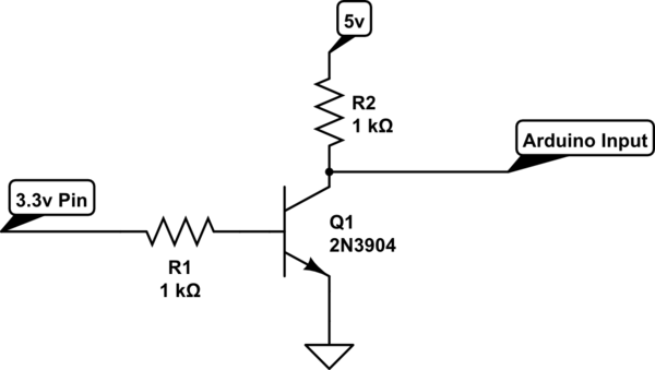
What would be the best way to step up my 3.3v relay signal to 5v? Could this be integrated into future pcbs?
 
Not sure which PCB design you’re using, but my latest designs break out 5V on a separate pin for this purpose.
I have some of your older boards (1-2 gen). The new boards will shift the cooling signal to 5v?
 
I have some of your older boards (1-2 gen). The new boards will shift the cooling signal to 5v?
Sort of — The signal itself coming off the microcontroller needs to be 3v3, but the relay boards have optoisolators built in to allow the 3v3 signal to switch a 5v signal which then in turn switches the relays.

The latest PCB design just has a 5V and GND pin broken out to make this a tad bit easier.

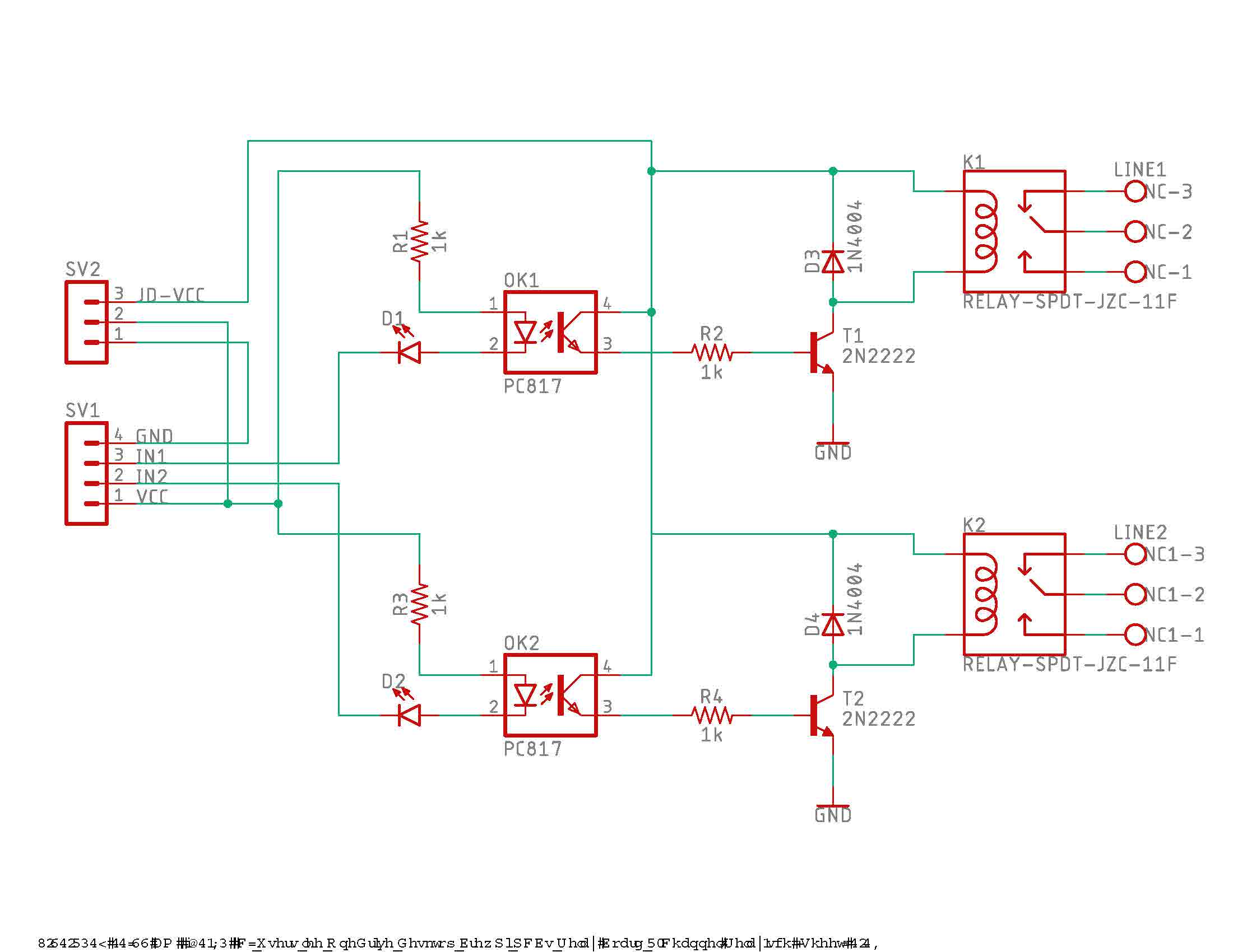
This is what @day_trippr ’s schematic was referencing — the JD-VCC pin on the relay board can be hooked up to 5V (with the jumper removed!) and you will be driving the relay with 5V. If you have a convenient way to break out a 5V line to go to the relay board with your current PCB then you don’t need a new design - hook that up and you’re golden.
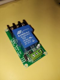
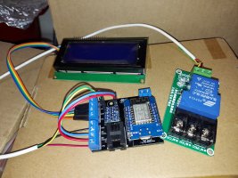
This is the relay I am hopefully going to use. I haven't found a clear schematic yet, but the jumper just says high, com, low, triggers. Don't know if their the same yet.
 

Attachments

  • 20220804_123624.jpg
    20220804_123624.jpg
    953.6 KB · Views: 0
This is the relay I am hopefully going to use. I haven't found a clear schematic yet, but the jumper just says high, com, low, triggers. Don't know if their the same yet.
I have no experience with that board, but it looks like it might have an optocoupler wedged in there between the blue relay and the green screw terminal (the chip that has “354” written on the top) so I would guess that the design is able to be triggered with voltage lower than 3v3 (and use higher voltage to then subsequently drive the relay). Not sure how you would hook it up though.

What are the labels for the green screw terminals?
Pos, neg, in1. Does have an optocoupler.
 
Pos, neg, in1. Does have an optocoupler.
I think I'm mistaken. This design uses the optocoupler in order to allow for both high and low-level triggering (hence the high/low with the jumper) -- not for allowing decoupling of the signal and the power to drive the relay itself.

You could still make this work by adding a level shifter somewhere, but it's going to be additional hardware beyond the basic PCB design.
Do you remember on you older pcbs w/shifter do they use all the channels?
 
No offense intended (maybe I'm not following), but I need my 3.3 i/o to step up to a full 5v for a higher amp relay to switch.

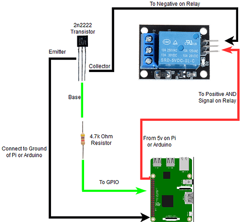
The circuit provides 5V across the relay coils, using an opto-coupled input sufficient to respond to 3.3V signalling levels. By noting the respective voltages I assumed you would follow the rails and arrive at the above conclusion. And if you don't want the optocoupler, drive the resistor at the base of the 2222 with the 3.3V control.

The relay pictured almost certainly uses the circuit I provided, btw. You can see the optocoupler and a 3 pin sot that's surely a transistor of some type. Judging by the trace sizes going through the three pin header, I bet that picks from the NO and NC relay pins and not actually changing the relay behavior...

Cheers!
 
Last edited:
The circuit provides 5V across the relay coils, using an opto-coupled input sufficient to respond to 3.3V signalling levels. By noting the respective voltages I assumed you would follow the rails and arrive at the above conclusion. And if you don't want the optocoupler, drive the resistor at the base of the 2222 with the 3.3V control.

The relay pictured almost certainly uses the circuit I provided, btw. You can see the optocoupler and a 3 pin sot that's surely a transistor of some type. Judging by the trace sizes going through the three pin header, I bet that picks from the NO and NC relay pins and not actually changing the relay behavior...

Cheers!
So your saying if I remove the jumper and jump 5v supply to the high pin it should switch properly? With the jumper removed, I already have 5v on the high pin?
 
This is what I'm saying: the jumper on that relay module may select which relay point to use, which is analogous to inverting the control response without the complexity...
1659710928790.png

To know for sure would require an ohmmeter...

Cheers!
 
Finally attempting my first dry run with Fermentrack, I tried to set up v0.14 serial and had a 66.8 degree offset on the beer temp probe (was reading 3.2 F) that I could not adjust for (wouldn't allow any value).

I also tried the v0.14 Low Delay, but as it is Wi-Fi only and for some reason the communication between the Pi and the Wemos fails every time it tries to update the controller.

I am back to the v0.11 serial and it appears to be working fine.

I am using a Glycol Chiller for my set up and I found that if I have the Chamber temp probe in the glycol(34 F) the SW thinks the "fridge" is too cold so it will not start the cooling cycle (pump in the glycol to the cooling coil in the conical).
I Have the beer temp probe in the thermowell, and the chamber temp probe slipped in between the conical and the neoprene insulating jacket, which the SW liked.

Will see how everything goes over the next couple of days.
 
This is what I'm saying: the jumper on that relay module may select which relay point to use, which is analogous to inverting the control response without the complexity...
View attachment 776929
To know for sure would require an ohmmeter...

Cheers!

I actually think that this is the schematic for that relay board:

Screen Shot 2022-08-06 at 8.32.40 AM.png


The jumper doesn't seem to select which relay point to use -- both are broken out -- it actually inverts the signal going to the relay.
 
The P3 header clearly allows selecting between using the NC or NO points.
Haven't figured out the other headers can change "polarity" vs the gpio input...

Cheers!
 
The P3 header clearly allows selecting between using the NC or NO points.
Haven't figured out the other headers can change "polarity" vs the gpio input...

Cheers!
It appears Thorrak has the correct diagram for this relay. Dc+ directly feeds low jumper and dc- feeds the high jumper pin, the com pin also goes through a 1k resistor to the opto
 
Last edited:
Back
Top