chucknorris101
Well-Known Member
- Joined
- Jul 17, 2014
- Messages
- 95
- Reaction score
- 16
I did above? Or is there another angle needed? I did a double replyLooks fine to me - can you send a close up of the cable ends though? 4.7k is perfect

I did above? Or is there another angle needed? I did a double replyLooks fine to me - can you send a close up of the cable ends though? 4.7k is perfect
Apologies - I see it now!I did above? Or is there another angle needed? I did a double reply
 .
. i loaded the sensor test and wifi reset - it appears it ran, the relay clicked on and off for both hot and cold, no change in the screen - how do i find the log for this?Apologies - I see it now!
I don’t know what to tell you.
Have you tried running the wiring test firmware with the LCD attached?
i loaded the sensor test and wifi reset - it appears it ran, the relay clicked on and off for both hot and cold, no change in the screen - how do i find the log for this?
thanks. yes it matches the pcb alignmentThe output is to the LCD screen itself, unfortunately... I see you’re using the “spark fun” style board - are you sure you have the high and low voltage sides on correctly? That’s the only other idea I have...
Hi - I am new to this thread but currently use a ‘Legacy’ BrewPi (RPi + Arduino) solution for my fermentation temperature control. I am looking to build a new chamber and see that there is this ESP8266 hosted solution.
I love what I am reading here but like all long threads in Forums, it is difficult to cut to the chase, buy the parts needed - including circuit boards if available and build the controller. Then what are the steps needed to flash the code and configure it? Is there a link to a ‘how to’ guide anywhere?
Thanks,
Paul
Hi - I am new to this thread but currently use a ‘Legacy’ BrewPi (RPi + Arduino) solution for my fermentation temperature control. I am looking to build a new chamber and see that there is this ESP8266 hosted solution.
I love what I am reading here but like all long threads in Forums, it is difficult to cut to the chase, buy the parts needed - including circuit boards if available and build the controller. Then what are the steps needed to flash the code and configure it? Is there a link to a ‘how to’ guide anywhere?

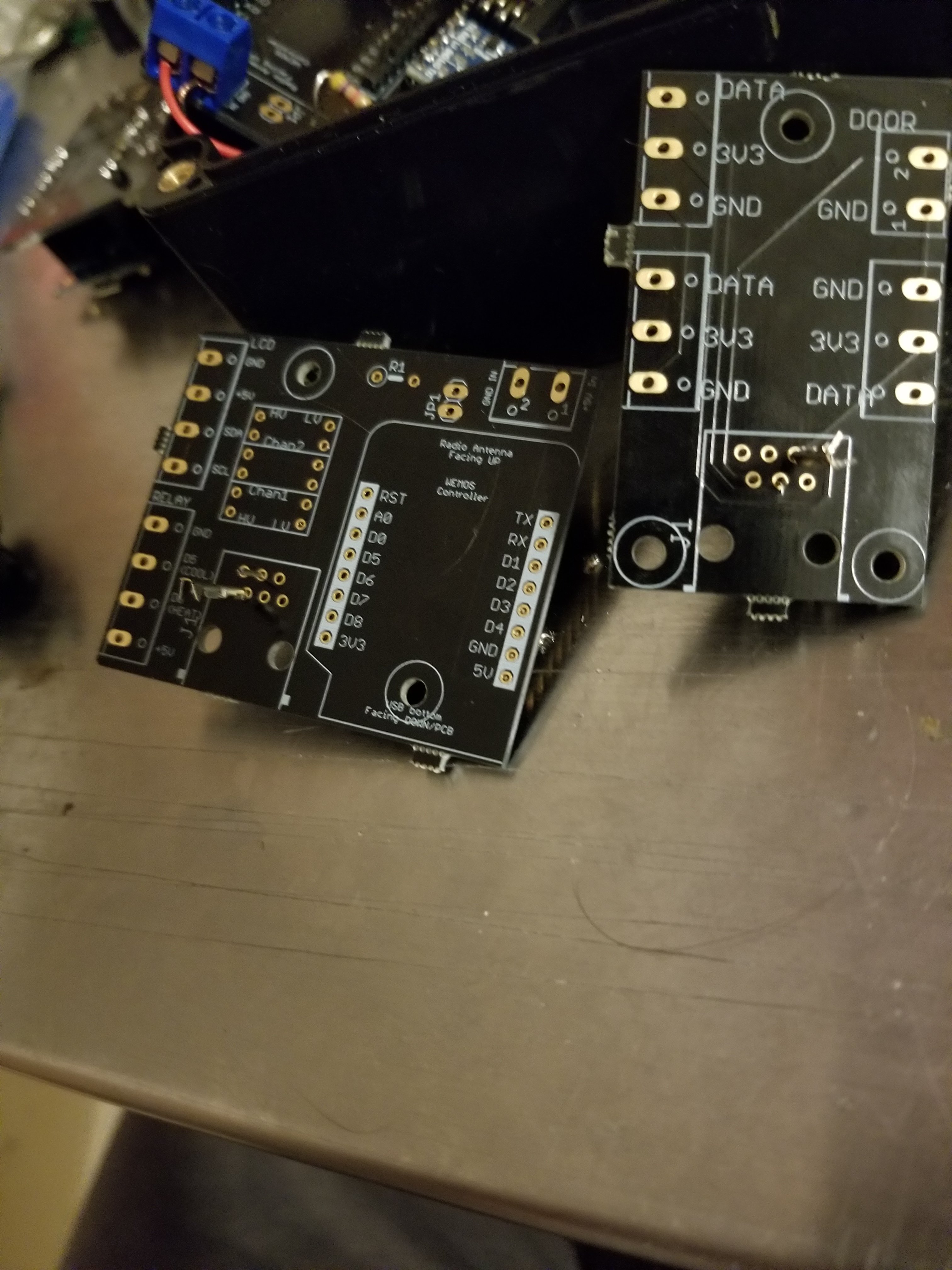
The main changes I made were:
- Remove ALL RJ-11 connectors in favor of RJ-45 (this will mostly eliminate the crossover vs. straight issue)
I may steal this for the documentation
I may steal this for the documentation
No, the mark up is the important part.Steal Away. If you want a pic without my mark up, let me know.
The RJ45 jacks were the last pieces I needed. When they arrived and wouldn’t line up with the PCBs...OMGosh, I was crushed!
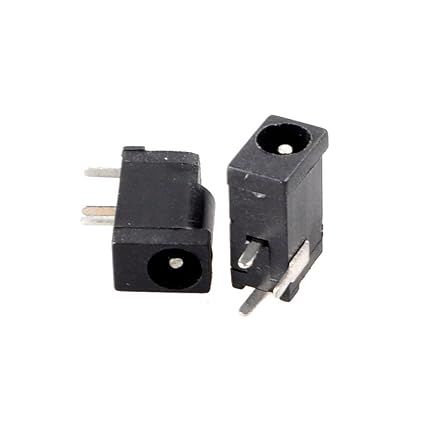
Would one of you mind explaining the difference?

Because I bought these RJ12 jacks for a separate project and was just wondering...
View attachment 655144
Will the older RJ11 boards be available? I placed an order for RJ11 boards last week and still have not received them. I tried to search for the board I ordered and did not see it. I have RJ11 temperature sensors already so would rather not change to the RJ45 if possible.As a side note - based on the trouble you were having @chucknorris101 I decided to spend today going through and revamping all of the board schematics. It won't help you out since you already have your boards, unfortunately, but hopefully it will help out newcomers to the project.
The main changes I made were:
Everything is available for order at pcbs.io - let me know if you have any issues!
- Remove ALL RJ-11 connectors in favor of RJ-45 (this will mostly eliminate the crossover vs. straight issue)
- Redesign all the boards (except the no-LCD board) to use the same basic screw "footprint" (they will all now fit the 3D printable case I posted awhile back)
- Update the hardware on the "sparkfun" boards to the latest version of their level converter
- Add logos to everything (look at that sexy gold logo up above!)
- Add/update Eagle board/schematic files to the repo
- Updated all the resistors for OneWire to 4.7k
Yep - they should all still be available. Which one are you not seeing (and where are you not seeing it)?Will the older RJ11 boards be available? I placed an order for RJ11 boards last week and still have not received them. I tried to search for the board I ordered and did not see it. I have RJ11 temperature sensors already so would rather not change to the RJ45 if possible.
Yep - they should all still be available. Which one are you not seeing (and where are you not seeing it)?
Awesome! This one. I could not find it in the GitHub fermentrack documentation. When I searched “fermentrack” and “Thorrak” on the pcbs.io website it did not show up.
Double checked my order and shows “in fabrication” so I guess I am still good to go.
D1 Breakout - No LCD TH Screws
Here is everything tagged “Fermentrack” on PCBs.io: https://pcbs.io/search?tag=fermentrack
That should include both the new and historic boards.
Hi Thorrak. I've been looking at doing a Fermentrack build for a long time. Amazing contribution.
I'm having problems creating an order from pcbs.io... every time I attempt there is a problem processing the payment. Is there another way to get the boards?
Also, minor point.. on Github the the links for the sensor boards lead to the other board (if you know what I mean) i.e the RJ45 link leads to the board for the RJ11 and vice versa.

Thanks for all your help! still waiting on screen 2, but both controllers are now working and recording with replaced level shifter and manual breakout connectors! one question, i remember somewhere about glycol settings, where can i find that/what do i need to change?
one weird thing. the lcd wont initialize with a bad or missing level shifter, but will read fine if removed under power....
Hi guys,
I read through the whole forum now and tried a clean installation of Fermentrack. I run a winery and I need process cooling for my fermentation tanks. I use standard china thermostates with NTC and 12V ball valves at the moment.
I plan to set up a digital solution now and searching for the right software for a long time.
So I thought about using Fermentrack to setup the cooling controllers for about 50 tanks. But I'm not sure yet if Fermentrack is the right solution for that.
I think there's no point in using 50 ESP controllers with 12v relay, is there a solution to use like a onewire relay board with 16 relays on one ESP8266? Do you think it's possible to run a 16ch relay board with one ESP8266 with 16 DS18B20 connected to one ESP8266?
Actually all I want is to log fermentation temperatures and control different fermentation temperatures for different tanks...
Do you have any suggestions for me?
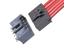
The bare stripped wires are crimp or soldered to a pin then inserted into the connectorHow do you hook the molex sensors up to the temp sensors though?
Enter your email address to join: