Motorized Monster Mill Build

Homebrew Talk - Beer, Wine, Mead, & Cider Brewing Discussion Forum

Help Support Homebrew Talk - Beer, Wine, Mead, & Cider Brewing Discussion Forum:

This site may earn a commission from merchant affiliate links, including eBay, Amazon, and others.
Good motor source is amazon. Grizzly G2532 1hp TEFC capacitor start motor 56 series for $171 shipped. Mine is a tank on my MM3-2.0. 30 lbs in the hopper and it will start and stop no problem. What sucks is I didn't see this thread with the well priced gear reducer so my mill has belts and sheaves...
 
Finally got to start on mine! Assembled the cart, positioned the mill and motor in place, marked and cut through for the grain hole. Started to mount the mill, but my bolts are too long. So, this coming week, Ill get that fixed, do my wiring, and come up with something to mount the motor on to raise to the same level as the mill, and Ill post up pics!
 
I'm having trouble wiring up my motor for reverse.

Here's my first attempt, and this turns the same direction no matter which way the switch is.
attempt1.jpg

Here's my second attempt. This only turns if the switch is such that the wiring is the same as my first attempt (so, T1, T3, and T5 are Hot, while T2, T4, and T8 are Neutral).
attempt2.jpg

Is it possible to control a motor with only the single DPDT switch, and have it reversible? Is it a problem to have power to T1 and T3 (or T2 and T4) while T5 and T8 are not powered?

EDIT: Figured it out:
1) I had my wires mixed up on the motor side. Once I got the right colors in the right places, I could reverse the motor.
2) However, I don't think I can get this to work with a DPDT switch, I think I need a 3PDT (On-Off-On) wired like so:
attempt3.png
 
Thanks for the write up. My pieces are laid out now, just figuring out details and the last bits to get. Pics to come...
 
Last edited by a moderator:

Yes! I have assembled all of the parts from the OP's list and purchased the same motor. Everything is mounted and this thing will be a monster when done.

Struggling with the wiring at the moment though. The Marathon motor has seven leads (per the diagram on the motor):

LINE VOLTAGE 1
J10 Black
T4 Yellow
T2 White

LINE VOLTAGE 2
P1 Purple

LEADS JOINED
P2 Brown
T3 Orange
T8 Red

As wired, it runs perfectly, but in the same direction, no matter the switch setting. Thought I had it figured out, but that 7th wire is throwing me off.

I am out of my element and for surely lost. Anyone have a suggestion on how to wire this up?

Thanks!

Mike

P.S. Here is a link to Marathon's wiring diagram: http://www.marathonelectric.com/CnxDocRequest/PublishedPDF/52a105383ba.pdf

Did you read Note 1 to reverse T8 and J10 to reverse direction?
 
Did you read Note 1 to reverse T8 and J10 to reverse direction?

Thanks Fred. Appreciate your taking the time to respond.

The motor is running in the correct direction (fortunately) and the drum switch is reversing polarity. Unfortunately the motor is smarter than me and runs CCW whether the switch is in forward or reverse --- that's wired per the diagram on the motor casing (i.e. L1/L2/Gnd).

In DrunkenMonks original post the wiring diagram shows 4 wires connecting to 6 leads on his original Worldwide motor. The 1 HP Marathon motor from surpluscenter has 7 leads.

Just not familiar enough with starter coils, capicators, etc. to feel comfortable guessing.

Mike
 
From the PDF that 7th wire is the output of a thermal overload wired in series with one motor winding. You could wire around it and have the original 6 wires to simplify comparing to drunken monks diagram.
 
Another way to say it is wire the purple wire to where he shows the blue wire landing the key is the other red and black wires going to the middle barrel terminal terminals to allow reversal. The brown to purple junction is provided to "simplify" end user connection to line voltage but is simply an extension of the blue wire but adding a thermal overload in the circuit. It is not a capacitor
 
A third way to say it is don't use the purple wire at all. Wire the brown and orange to the terminal he shows blue and orange going to. But you have to split out the black and reds from their 3 wire junctions
 
Thanks Fred. That was the information I needed.

Who knew brewing beer would lead to an understanding of industrial motors?

Based on your posts and some study of the motor and RS-1a wiring diagrams, I learned that only the starter leads reversed polarity. The main leads were constant.

Wired everything up this evening after work and can confirm for anyone using the Marathon EG282 motor, that the Purple wire (P1) can be substituted for the blue wire in Monk's original wiring diagram. I simply taped the Brown wire (P2) off.

Works fine. Not that reverse will ever be needed, but it is available.

Thanks so much for the help.

Mike
 
I'm confused with how to wire my switch (Dayton 2X440A, wiring diagram in picture attachment #5) & motor (Marathon 5KCR48UN0102Y) and could use some help.

From the input power cord (Black=Hot 240v, White=Neutral, Green=Ground) I have the black connected to switch pin 2, white connected to pin 6, and green connected to grounding screw of the switch. Pretty sure that is correct (note that i'm in europe, but my colors are off american standards). Picture #1 shows this.

Now this is where i'm confused. What pins from the switch do i connect to motor terminals (see picture #2)? As you will see in the pictures, my motor does not have all the wires just loose, rather there are terminals & jumpers. Here is a diagram of how the terminals are connected (please take note that my motor is configured for "hi voltage" thus the wiring diagram follows "NOTE #1" in the following link, and as you can see in my attached picture):
http://www.globalindustrial.com/site/images/universal/PEM/EG277-Conn.pdf

My current thought is that i should connect switch pin 5 to motor connection point "2" (the lower screw terminal) but not sure about that since white (T2) is connected to terminal "5" due to "hi voltage" mode. Then i'm thinking switch pin 4 should be connected to motor terminal "5" which is red (T8). switch pin "3" to terminal C black (T5) and switch pin "1" to motor terminal "5" as well -- but that is the same motor terminal i think i should connect switch pin 4 to. And my upper screw terminal (that P1/purple goes to) has no connection at all with this scheme. Grounding it is obvious.

Thank you in advance!

photo1.jpg


photo2.jpg


photo8.jpg


photo9.jpg


photo10.jpg
 
I followed the setup as the original post except I wired my switch for forward and reverse. Here are some pictures of my setup.

image.jpg
 
I would say it's overkill personally. When you gear it down to a reasonable speed there's no way you'll need 1/2 HP. I guess the voltage is convenient though. The voltage may limit you if you ever wanted to put it on something else.
 
I would say it's overkill personally. When you gear it down to a reasonable speed there's no way you'll need 1/2 HP. I guess the voltage is convenient though. The voltage may limit you if you ever wanted to put it on something else.

Overkill is one thing...I just like the price :) I like the clean look of the gear reducer (which is awfully spendy in its own right) and notice that this motor runs a bit slower than the OP's motor. Not sure if that 200 RPM difference will have an effect after it is reduced?
 
Berrywise the rpm difference depends on how you plan on reducing it. I used a 1725 motor and a 10:1 reducer. That reducer would put you at 142 rpm might be too slow. Or you could go the pully route. Just my opinion. I over thought building my mill wayyy too much but looking back it was worth it.
 
1/2 hp is far from overkill..... My mill requires a 1 hp motor(MM3-2.0)

I have the MM-2, two six inch rollers. Will 1/2 hp be enough I guess is the question. Anyone have thoughts? I'm currently using a drill from harbor freight and just looking to clean up the look a little (yes I'm petty like that).
 

Berrywise, note that the listing is for a 50 Hz motor. If you're in North America, you probably have a 60 Hz power source.

A 50 Hz motor run on a 60 Hz supply will spin faster (20 %) and may heat up more. Probably not an issue in your use, but be sure to figure that in calculating your gear reduction or pulleys. If heat is a problem, you may be able to mitigate it with an additional fan and/or heat sinks or reducing your run time.

You can read more about it here:
http://www.engineering.com/ElectronicsDesign/ElectronicsDesignArticles/ArticleID/8154/Changing-an-Induction-Motors-Power-Supply-Frequency-Between-50-and-60Hz.aspx
 
Hello,

This thread has been wonderful in helping me add a motor to my MM3 Grainmill. However, I am struggling with the wiring of the reversing switch. Any help would be greatly appreciated.

I am using the same reversing switch as the Original Poster (from McMaster). And I am using this motor from surplus center: https://www.surpluscenter.com/Electrical/AC-Motors/AC-Motors-Face-Mount/1-HP-1800-RPM-115-230-VAC-56C-TEFC-LEESON-MOTOR-W-MANUAL-OVERLOAD-10-2706.axd

I have uploaded a pdf of the motor's wiring diagram to this post. Here is also a link to it: http://www.leeson.com/CnxDocRequest/PublishedPDF/grf_swd-0130015736_00500303_402810276_355.pdf

Thanks in advance for any help,

Bryan

View attachment M6C17FK80E Connections.pdf
 
Hello,

This thread has been wonderful in helping me add a motor to my MM3 Grainmill. However, I am struggling with the wiring of the reversing switch. Any help would be greatly appreciated.

I am using the same reversing switch as the Original Poster (from McMaster). And I am using this motor from surplus center: https://www.surpluscenter.com/Electrical/AC-Motors/AC-Motors-Face-Mount/1-HP-1800-RPM-115-230-VAC-56C-TEFC-LEESON-MOTOR-W-MANUAL-OVERLOAD-10-2706.axd

I have uploaded a pdf of the motor's wiring diagram to this post. Here is also a link to it: http://www.leeson.com/CnxDocRequest/PublishedPDF/grf_swd-0130015736_00500303_402810276_355.pdf

Thanks in advance for any help,

Bryan

I worked up this switch wiring diagram a while back for a Leeson motor. It's not using the OP's switch, but it might give you some ideas.

leeson-motor-grain-mill-wiring-64630.jpg


I don't have a diagram of the contacts for your switch.
 
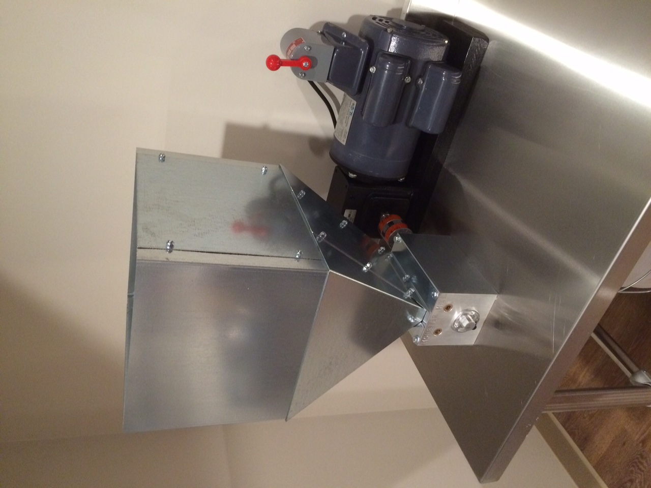
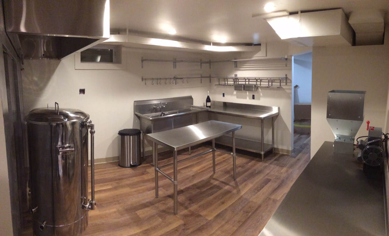
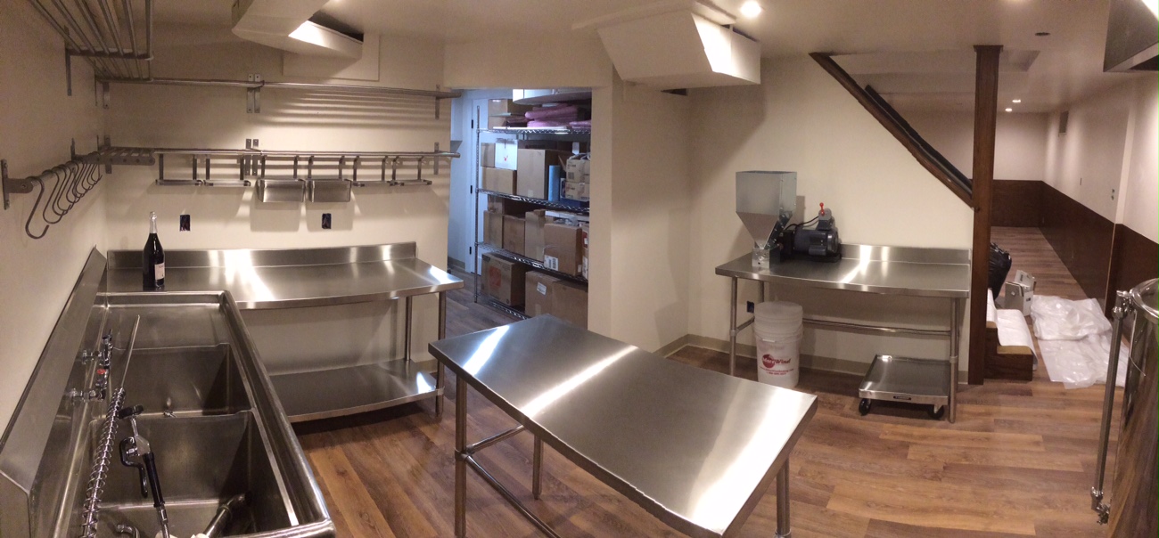
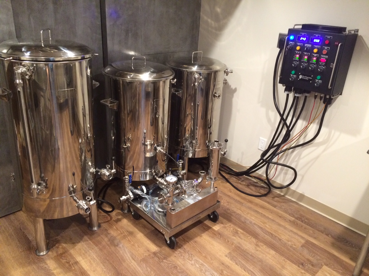
Ok ... so I moved from CA to NY, sold almost all my old equipment to my friend, had a clean slate, and decided to crank it up a notch! I'm building a new brewery with 1 BBL Stout tanks and an electric setup from theelectricbrewery.com. More than just buying the controller from Kal, his set-up also inspired me to use lots of pretty stainless steel (which is a lot cheaper these days) and build a new mill station in the progress.

My original set-up worked great, but there's always room for improvement:

Here's some notes on the build:
  • Mill and motor arrangement fit perfectly on table understructure. This wasn't planned. I just got lucky!
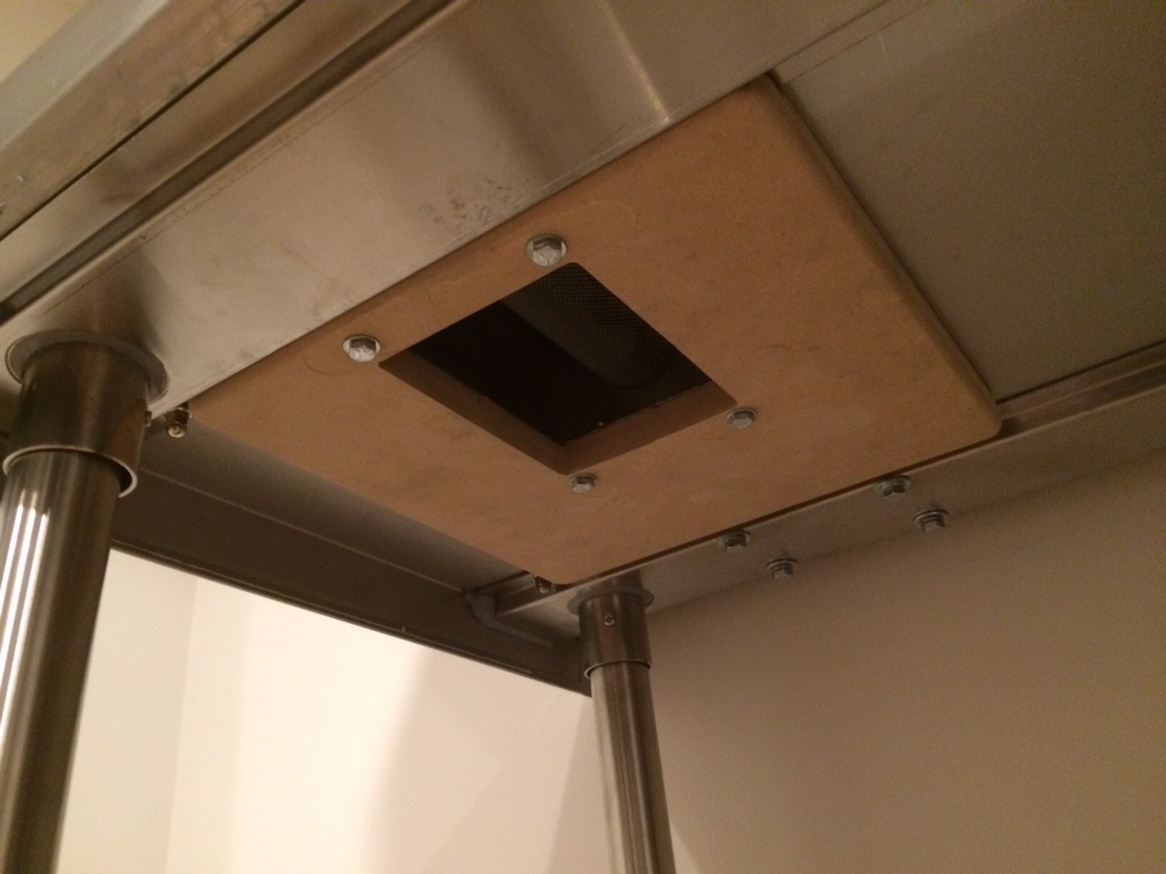
  • Monster now ships a thick MDF baseplate with their mill (sized to fit the top of a bucket I suspect). This is a needed addition. It's not as bad as a Barley Crusher, but Monster Mill rollers will pinch and jam if the base the mill is attached to isn't flat or flexes. This MDF board fixes that.
  • I attached the MDF board to the bottom of the table and bolted through it to the mill. It helps stiffen the thin steel table top and fits almost perfectly between the table structure rails (see photos).
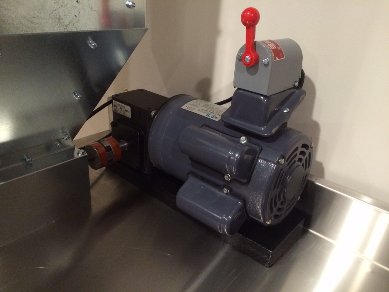
  • Motor doesn't have a base which was a little bit of an oversight on my part. I decided to instead mount off the gear reducer housing which worked just as fine.
  • Spacer to set height of gear reducer shaft to line up with mill shaft is hard wood (oak). Even though it's only attached through the bolts on the gear reducer housing, it extends under the motor to spread out the footprint on the table top to reduce bending. Also, if needed, I can wedge a spacer in between the wood and the motor if the motor bounces around too much (but it doesn't look like that will be a problem).
  • Bolts to bottom of gear reducer line up with edges of under table support rail which helps stiffen the motor mount (see photos). Again, I got lucky here and that wasn't planned.
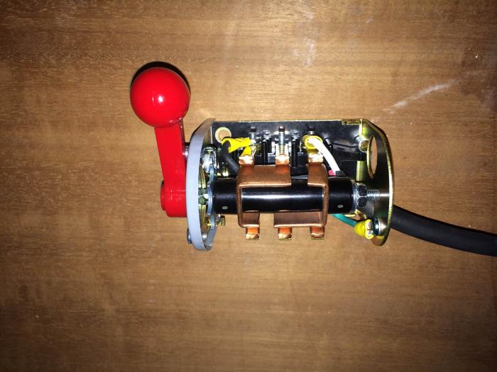
  • For more usable table space and a cleaner look, I mounted the switch to the top of the motor electrical box.
  • Even though the motor was different than my first build, the wiring was almost exactly the same. The motor had the same color wires and T numbers. I did have to switch two wires to reverse the direction of the motor, but that was very easy to figure out based on the wiring info right on the side of the motor.
  • Although the stainless steel table looks super cool and was easier to buy than make, cutting through the thick gauge stainless steel top takes a little time (and I didn't want to screw it up!). To cut the rectangular hole for the grain, measure 4 or 5 times and cut once. I took it nice and slow with a Dremel and a tiny cut-off wheel. You could probably cut it faster with a hand grinder and cut-off wheel if you're steady handed. Drilling also requires patience. Start with a pilot hole, use cobalt steel bits, and use lots of lubricant or cooling fluid.

Enjoy!
 
Motor will work but expensive. Check ebay should find something around $130. My reducer doesn't have a base and I haven't had any issues. When you attach it to the motor and mill its not going anywhere.
 
Back
Top