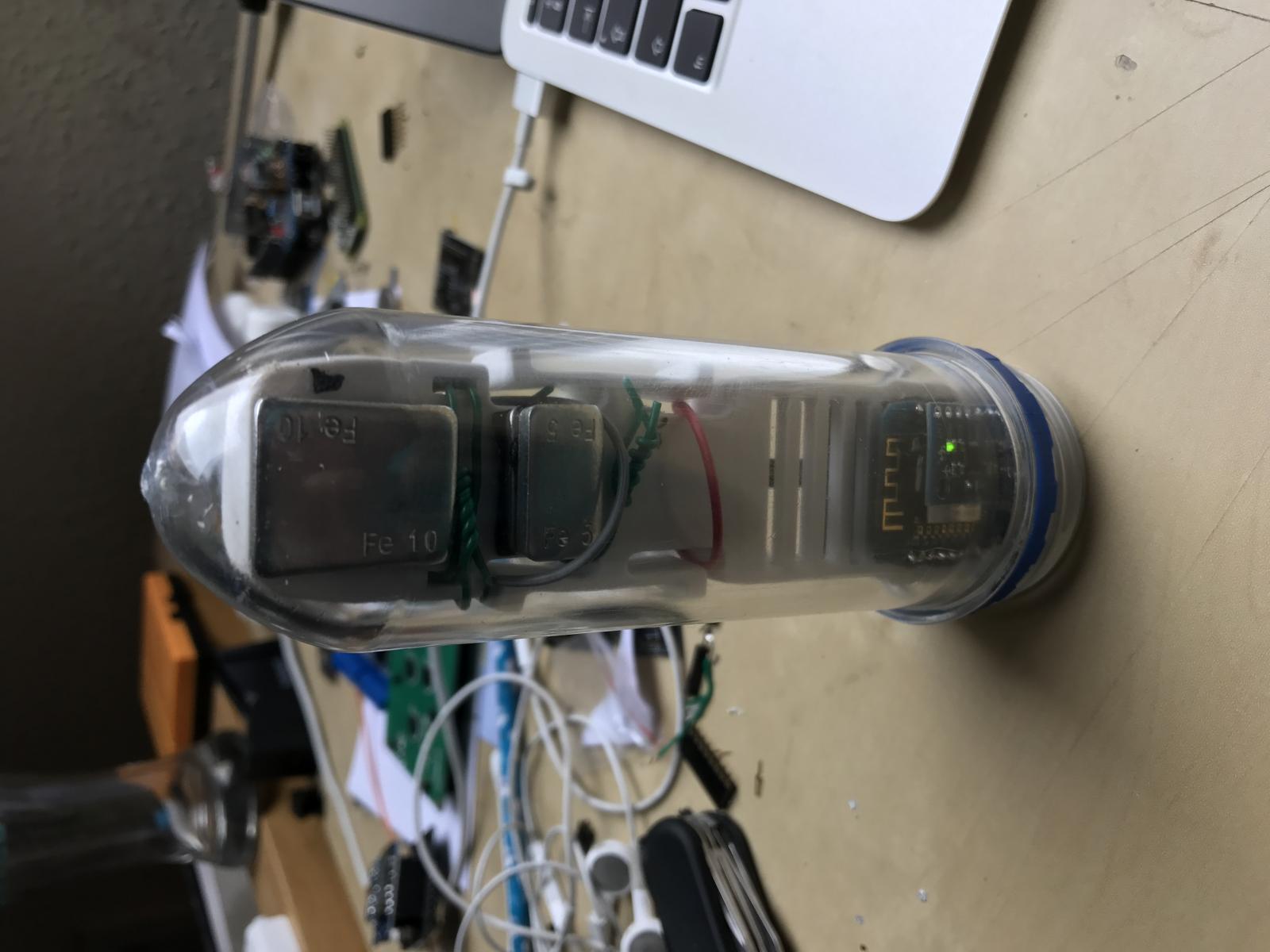
iSpindle - DIY Electronic Hydrometer

Homebrew Talk - Beer, Wine, Mead, & Cider Brewing Discussion Forum

Help Support Homebrew Talk - Beer, Wine, Mead, & Cider Brewing Discussion Forum:

This site may earn a commission from merchant affiliate links, including eBay, Amazon, and others.
Hello,

I also have exactly the same problem.
I've already set it to different update values (20sec. to 15min.)
Now I've also changed the 470ohm resistor with a schottky diode (ring to D0) and still the same problem.
Can anyone give some more help?

I don't know what you mean by "ring". If it is the circle mark on the diode, then you put it in wrong direction.
TL;DR
D0 is controlled by RTC, the part that counts time when ESP8266 sleeps. When its time to wake-up, RTC sends signal to RST(Reset) by D0. If the signal can't be sent to RST for some reason, ESP8266 won't wake-up.
 
Shouldn't the formula be a trigonometric one that you happen to be approximating with a polynomial? Since we're turning moment arms into angles. A cubic is probably close enough, but you might get a fit with fewer parameters in the model that way.

I should probably work out the physics, since I am a physicist...

Someone already did that, check it out:
http://hobbybrauer.de/forum/viewtopic.php?f=7&t=11235

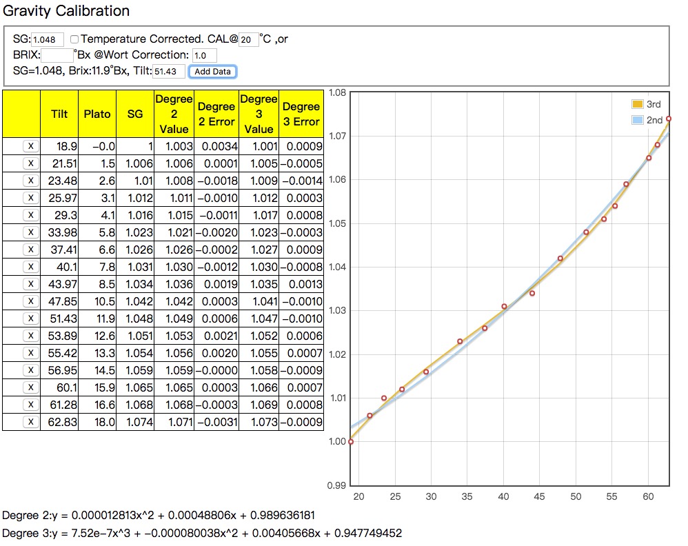
I am using a cubic formula because it gives me better result.

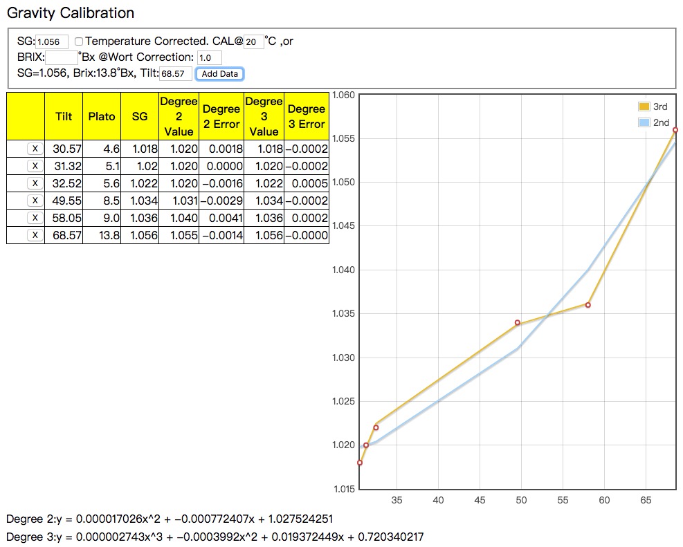
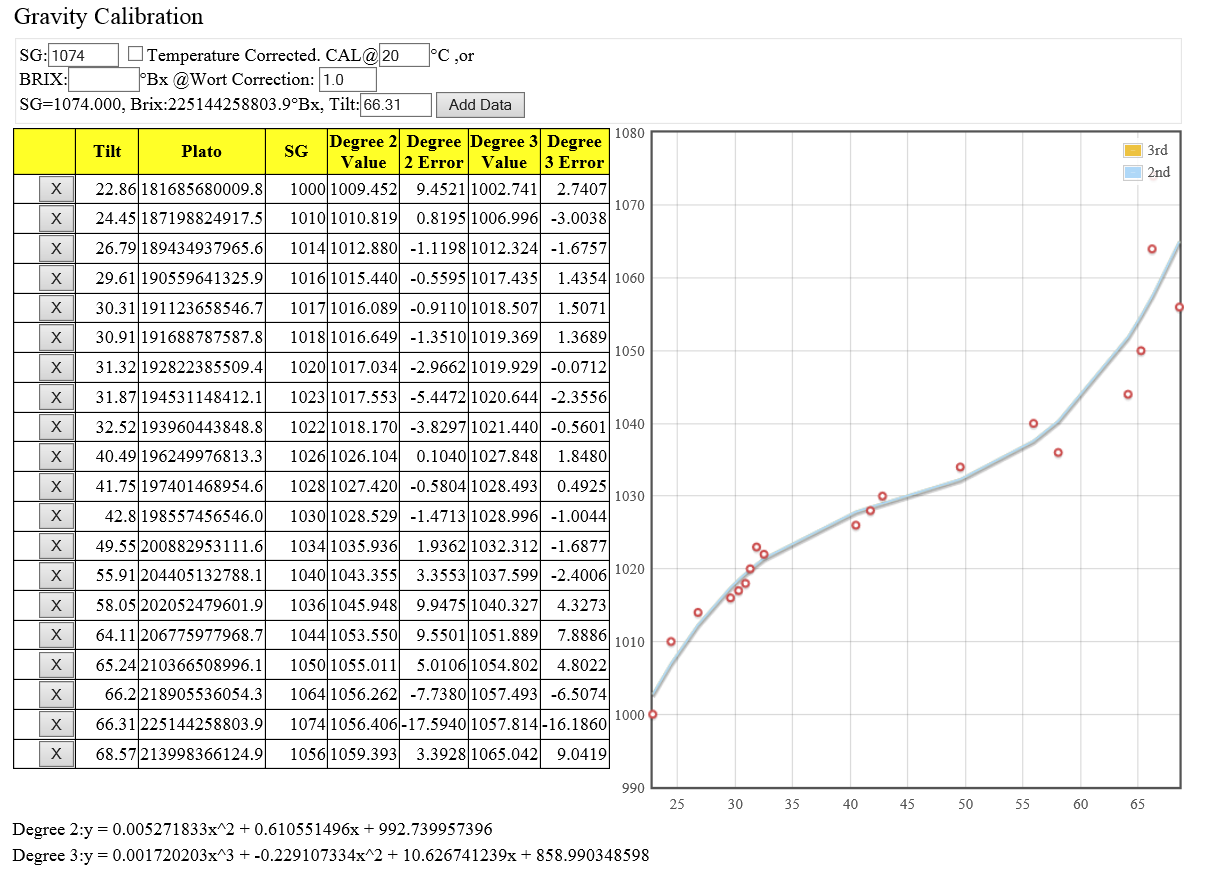
The polynomial regression runs so fast that I tried to derive a cubic and a quadratic formula at the same time. You can find that most errors of the cubic formula are within 1 point, and the maximum is 1.4 point. The maximum error of the quadratic formula is 3.4 points, and a half of the errors exceed 1 point.
I am an engineer, so I choose to believe in the fact, not the theory.

[Updated: although the result was correct, the displayed lines were wrong. This is the corrected one.]

cal-r.jpg
 
I don't know what you mean by "ring". If it is the circle mark on the diode, then you put it in wrong direction.
TL;DR
D0 is controlled by RTC, the part that counts time when ESP8266 sleeps. When its time to wake-up, RTC sends signal to RST(Reset) by D0. If the signal can't be sent to RST for some reason, ESP8266 won't wake-up.

Yes this is what i meant (ring/circle mark).
OK, always thought it was in that way, I will change it and see if it helps.
Thx for the info.
 
Someone already did that, check it out:
http://hobbybrauer.de/forum/viewtopic.php?f=7&t=11235

I am using a cubic formula because it gives me better result.

The polynomial regression runs so fast that I tried to derive a cubic and a quadratic formula at the same time. You can find that most errors of the cubic formula are within 1 point, and the maximum is 1.4 point. The maximum error of the quadratic formula is 3.4 points, and a half of the errors exceed 1 point.
I am a engineer, so I choose to trust the fact, not the theory.

So do you have an excel sheet or something to try out, or how to use the more complex ploynium?
 
My first run on an US porter, 10 L with 10gram yeast!

Control measuments:
26 maj kl. 14.45, OG= 1056 (tilt=68,85)
27maj kl. 11.25, G= 1056 (Tilt=68,57
28maj kl. 13.10, G=1036 (Tilt=58,05)
28maj kl. 18.55, G=1034 (Tilt=49,55)
29maj kl. 14.45, G=1022 (Tilt=32,52)
29maj kl. 22.10, G=1020 (Tilt=31,32)
30maj kl 6.45, G=1018 (Tilt=30.91)
30maj kl. 22.00, G=1018 (Tilt=30,57)
4june, G=1017

Regarding Polonium then I used the one posted earlier for initial tilt of 23 from my sugar experiament, but had to remove the last 2 measument as they seem to be outliners!
E..g. -0.003147459*tilt*tilt+1.351450453*tilt+978.5847256 and had to add one point to the figure in red to get it to fit with control-measuments!

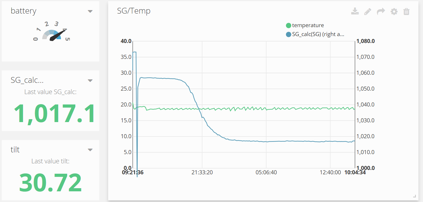
Is running a second bacth now, where hydrometer dsaid 1053 and Ispindel says 1056 (https://app.ubidots.com/ubi/public/getdashboard/page/HipoQxyH7NhTHfugz6wIYfvMSDY), so not super correct!

US_porter_1_week.png


7ee96be347161a75ad09f3cc97b638c8.jpg
 
So do you have an excel sheet or something to try out, or how to use the more complex ploynium?

I don't have access to MS excel, so I created a HTML/Javascript by using regression-js library. More complicated formula cab be generated, but I think cubic polynomial is enough.
 
I don't have access to MS excel, so I created a HTML/Javascript by using regression-js library. More complicated formula cab be generated, but I think cubic polynomial is enough.

Ok, tried to un your SG calibration htm file in browser (IExplore and crome Google), and can enter one data point and thereafter it will not accept more data.....do it need to run from a server, e.g. fro a brewpi?
 
Ok, tried to un your SG calibration htm file in browser (IExplore and crome Google), and can enter one data point and thereafter it will not accept more data.....do it need to run from a server, e.g. fro a brewpi?

No, but your computer must have access to internet, because the regression library is not embedded.

Here is the result of your dataset. BTW, I made a mistake by drawing the same dataset. Therefore, the drawing of my data set is incorrect. dyqik is right. The function should be more like an trigonometric(tangent?), and the line of cubic polynomial is more like trigonometric.

cal2.jpg
 
No, but your computer must have access to internet, because the regression library is not embedded.

Here is the result of your dataset. BTW, I made a mistake by drawing the same dataset. Therefore, the drawing of my data set is incorrect. dyqik is right. The function should be more like an trigonometric(tangent?), and the line of cubic polynomial is more like trigonometric.

Thanks, my computer is on the net, so not sure what I do wrong, but mankind always on the hunt for evolution! Anyway it seems to work very fine......and I am exciting to see how second batch will report at the end conta a hydrometer !
 
Btw,
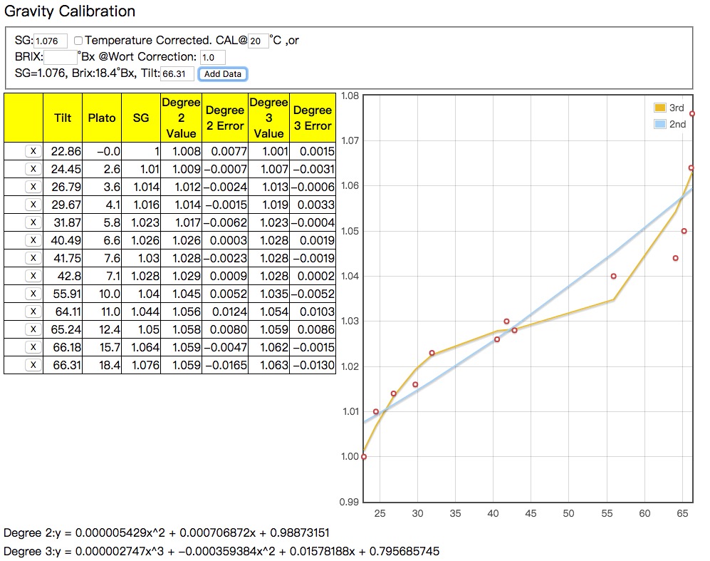
Pocketmon, could I get you to repeat it with the following dataset:
tilt sg
22,86 1000
24,45 1010
26,79 1014
29,67 1016
31,87 1023
40,49 1026
42,8 1028
41,75 1030
55,91 1040
64,11 1044
65,24 1050
66,18 1064
66,31 1076

Just for the fun :)
Klaus
 
No, but your computer must have access to internet, because the regression library is not embedded.
Its not working here, either. Win10, Chrome, Firefox or Edge. All updated.

BTW, I can add the first pair of data and the "Add data" button works well. If try to add the second pair of data, the button doesn't work anymore
 
Its not working here, either. Win10, Chrome, Firefox or Edge. All updated.

BTW, I can add the first pair of data and the "Add data" button works well. If try to add the second pair of data, the button doesn't work anymore

My bad.

Please download the regression.min.js from here:
http://tom-alexander.github.io/regression-js/

put the regression.min.js at the same folder of the html.

Sorry about that.
 
Btw,
Pocketmon, could I get you to repeat it with the following dataset:
tilt sg
22,86 1000
24,45 1010
26,79 1014
29,67 1016
31,87 1023
40,49 1026
42,8 1028
41,75 1030
55,91 1040
64,11 1044
65,24 1050
66,18 1064
66,31 1076

Just for the fun :)
Klaus

Something wrong ?
42,8 1028
41,75 1030

cal-kb.jpg
 
Well, I'm pretty surprised, it all seems to work, I've soldered 2 boards and no issues so far, battery charges, wemos works, I declare it a success :hs:

if anyone is interested in ordering a board, you can get them from here. it's about $7 for 4 with free shipping -> https://PCBs.io/share/8gbKR

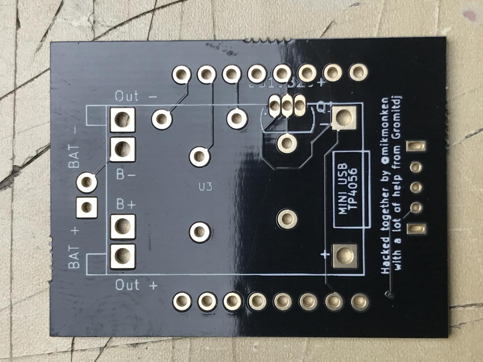
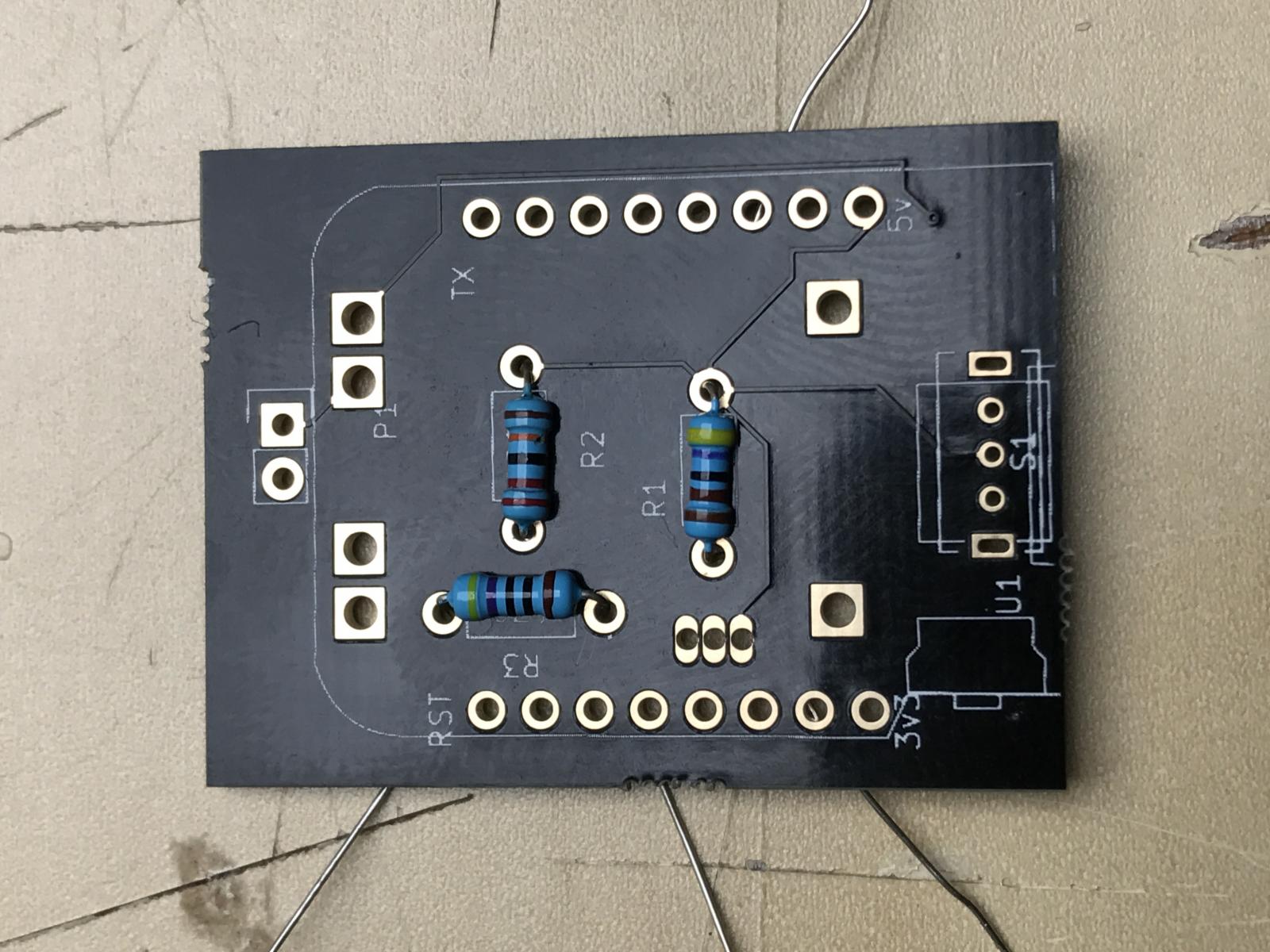
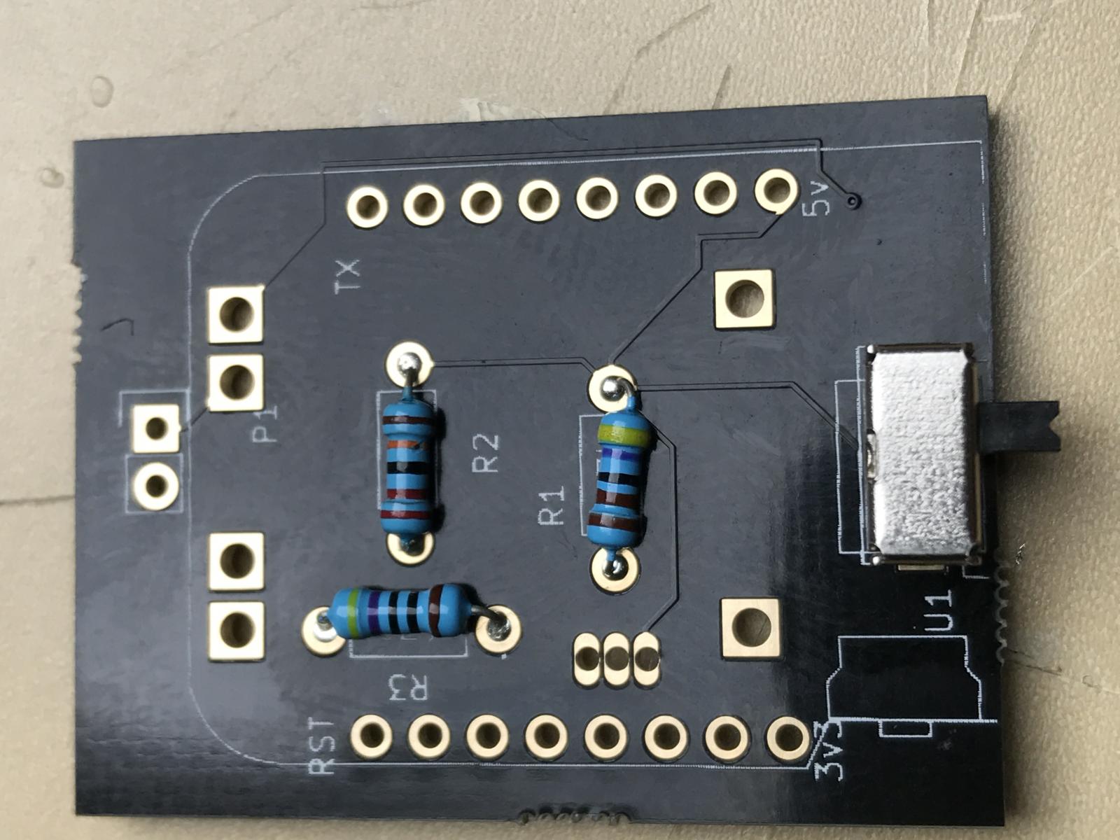
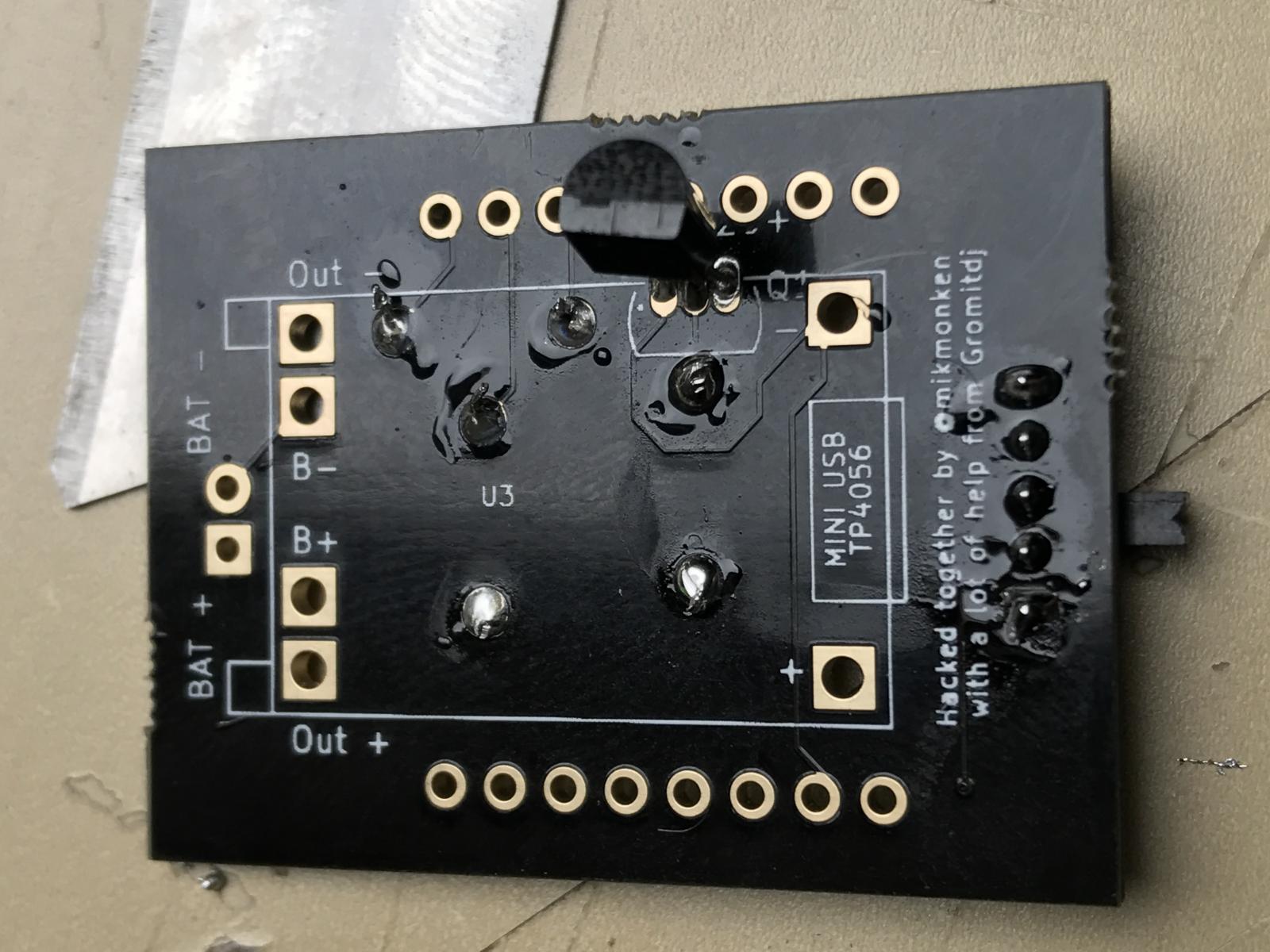
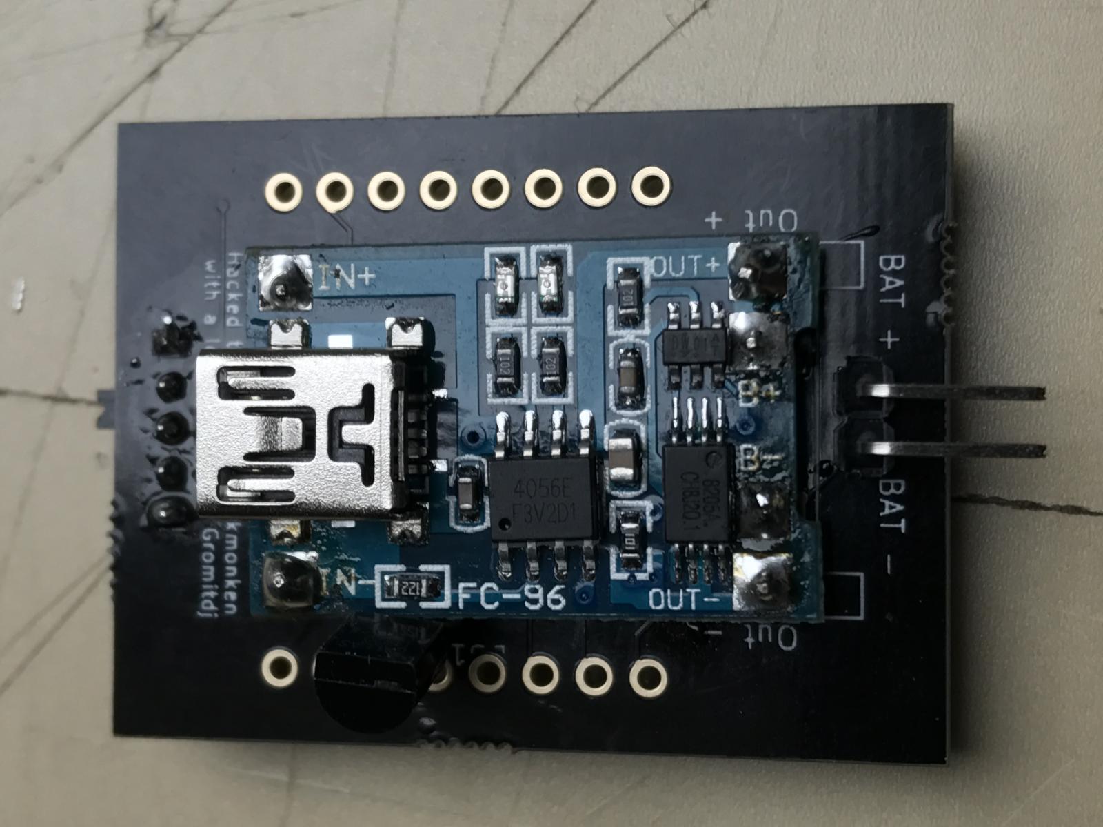
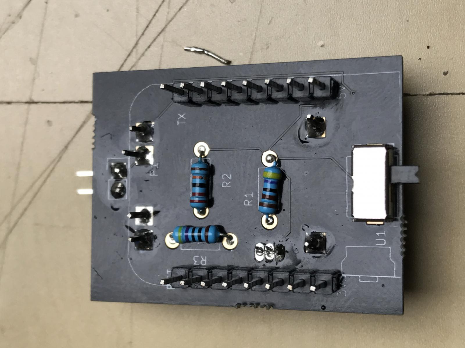
I've tried to mark everything up, my process for soldering was.

I'm assuming you've soldered the gyro onto the wemos already.

Resistors
Switch (which works :) )
Flip over and insert solder the temp probe
lipo charger next (you'll need to tilt the probe out of the way slightly)
battery charger pins (you can just solder wires directly into this if you choose)
then the headers for the wemos.

it's pretty simple to knock together. the switch and the lipo I had to make footprints for which are based on this Wishlist form Aliexpress -> https://my.aliexpress.com/wishlist/shared.htm?groupId=3110754426

although as you might see from the photo of the lipo board the one of used in the picture is recycled and not the one ordered so there is a chance other lipo boards would work, I found on my breadboard version the drill holes didn't line up perfectly.

I've got to say I'm pretty happy with it, it's much neater and easier to solder than the breadboard version.

IMG_0340.jpg


IMG_0338.jpg


IMG_0341.jpg


IMG_0343.jpg


IMG_0344.jpg


IMG_0345.jpg


IMG_0347.jpg


IMG_0350.jpg
 
Well, I'm pretty surprised, it all seems to work, I've soldered 2 boards and no issues so far, battery charges, wemos works, I declare it a success :hs:

if anyone is interested in ordering a board, you can get them from here. it's about $7 for 4 with free shipping -> https://PCBs.io/share/8gbKR

I've tried to mark everything up, my process for soldering was.

I'm assuming you've soldered the gyro onto the wemos already.

Resistors
Switch (which works :) )
Flip over and insert solder the temp probe
lipo charger next (you'll need to tilt the probe out of the way slightly)
battery charger pins (you can just solder wires directly into this if you choose)
then the headers for the wemos.

it's pretty simple to knock together. the switch and the lipo I had to make footprints for which are based on this Wishlist form Aliexpress -> https://my.aliexpress.com/wishlist/shared.htm?groupId=3110754426

although as you might see from the photo of the lipo board the one of used in the picture is recycled and not the one ordered so there is a chance other lipo boards would work, I found on my breadboard version the drill holes didn't line up perfectly.

I've got to say I'm pretty happy with it, it's much neater and easier to solder than the breadboard version.
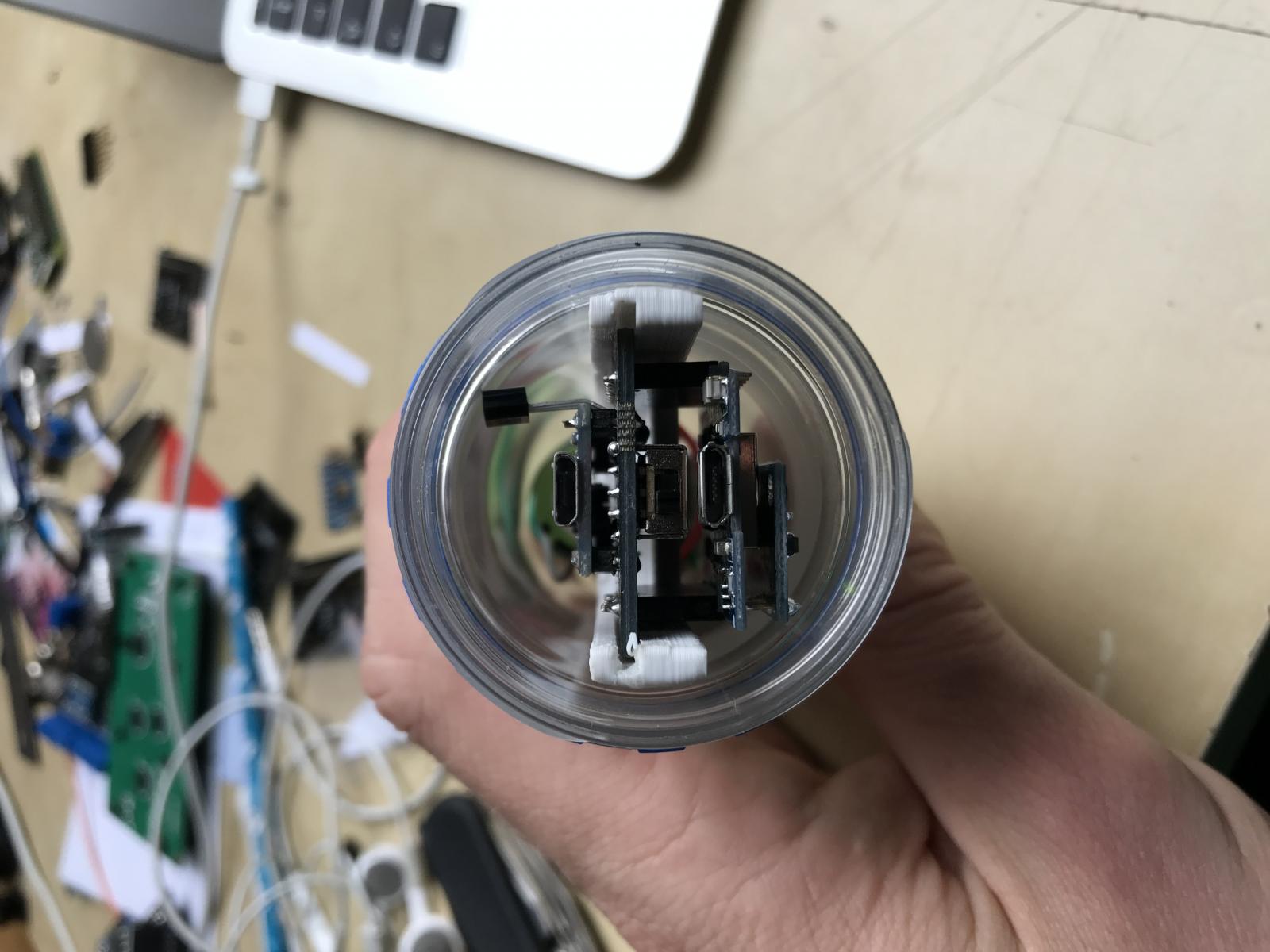
Do you happen to have a link to the bottle you are using? I think I may go ahead and get my parts on order. Nice job in the circuit board!
 
Hi Mikmonken,

Thanks for sharing your photos of the boards, which look brilliant, and I've place an order straight away with PCB.io.

One question, I would like to ask is I, I see you have all standard resistors, as I have been having problems with the deep sleep on mine, and had to use a BAT43 Schottky Diode in place of a 470 ohm resistor? Therefore, any feed back on this would be welcomed.

Thanks Again.
 
Hi agian, trowed all my data both sugar-solution and 1s run of the fast fermenting US porter of 10L with 10g yeast.

Seems it only draws 2nd line?

That is the mistake I mentioned.

Please get the file from Github again. I just updated it.
 
Hi Mikmonken,

Thanks for sharing your photos of the boards, which look brilliant, and I've place an order straight away with PCB.io.

One question, I would like to ask is I, I see you have all standard resistors, as I have been having problems with the deep sleep on mine, and had to use a BAT43 Schottky Diode in place of a 470 ohm resistor? Therefore, any feed back on this would be welcomed.

Thanks Again.


I guess you should be able to just swap them out, but I'm not sure which way the diode would need to face.

One thing I have noticed though in doing this, is that my wemos would not come out of deep sleep unless it was connected to the battery. I guess the USB to the lipo just isn't powerful enough to wake up the wemos?
 
Has anyone tried to build this with another board, such as Adafruit's Huzzah? The Huzzah looks to be .6mm narrower, 4mm shorter, and 5g lighter. I'm going to start ordering parts for this, so I can build it along with a Huzzah-based BrewPiLess.

Edit: Or what about the Adafruit Feather Huzzah, which adds the Lipo charging onto the same board as the ESP8266? Although it does do it in a linear, rather than stacked orientation so it's require different weighting and a different sled.
 
W
if anyone is interested in ordering a board, you can get them from here. it's about $7 for 4 with free shipping -> https://PCBs.io/share/8gbKR
great job
i was going to order but my pettlings are a bit narrower then this. Do you have the eagle file. i wouldnt mind trying to put the 5v line inboard so i can make the board fit my pettling
 
great job
i was going to order but my pettlings are a bit narrower then this. Do you have the eagle file. i wouldnt mind trying to put the 5v line inboard so i can make the board fit my pettling

Since I worked with @Mikmonken on it, I can tell you that it is not Eagle. It was done in KiCAD. That being said, it's not a complicated schematic if you wanted to recreate it in Eagle.
 
Since I worked with @Mikmonken on it, I can tell you that it is not Eagle. It was done in KiCAD. That being said, it's not a complicated schematic if you wanted to recreate it in Eagle.
no problem just being lazy. haven't played with kicad but looks like i can download it. what about the kicad file so i can make it much the same?
 
Well, it is @Mikmonken's file, so it would be up to him. You would also need all of the libraries that he developed.

And if you are familiar with Eagle, be prepared for some frustration in your transition to KiCAD. Honestly, if you are at all proficient with Eagle it may be quicker to start from scratch in eagle. I can provide the schematic we created.
 
I'm happy to share my files, just need to find somewhere to host them to avoid the clutter on my Dropbox. What size is your pelting though this design is 30x40
 
I'm happy to share my files, just need to find somewhere to host them to avoid the clutter on my Dropbox. What size is your pelting though this design is 30x40


Might be a false alarm. I remeasured my petting and it's just 31 mm so should fit. I'll order some as I'm going crazy soldering my project board. These will be so much easier. Thanks Mik
 
I don't know what you mean by "ring". If it is the circle mark on the diode, then you put it in wrong direction.
TL;DR
D0 is controlled by RTC, the part that counts time when ESP8266 sleeps. When its time to wake-up, RTC sends signal to RST(Reset) by D0. If the signal can't be sent to RST for some reason, ESP8266 won't wake-up.

I've changed the diode (Ring at RST) but now the LED on the Wemos doesn't blink anymore. Still no updates on Ubidots also.

FYI,
https://www.losant.com/blog/making-the-esp8266-low-powered-with-deep-sleep


Use your multi-meter to check the voltage of RST pin. That's what I can suggest.

I'm not sure this advice is right,

According to the link you gave

The RST pin is held at a HIGH signal while the ESP8266 is running. However, when the RST pin receives a LOW signal, it restarts the microcontroller. Once your device is in Deep-sleep, it will send a LOW signal to GPIO 16 when the sleep timer is up. You need to connect GPIO 16 to RST to wake up ( or reset ) the device when Deep-sleep is over.

GPIO16 is D0, so RST sends a signal to D0 meaning the diode must be orientated that way. This is the same advice as given here

instead of experimenting with resistors and relying on the "it worked for me" value, it would be more technically correct to use a schottky diode (e.g. BAT43) to cleanly pull rst low without sideeffects when gpio16 is high.

p.s.: the cathode (ring) towards gpio16

So the cathode should be orientated to D0. Or have i got this arse-about?

That being said I still haven't been able to test my setup in anger yet. I'm having gyro troubles :confused:

Well, I might be wrong. You choose what to do.
when the RST pin **receives** a LOW signal,
cleanly **pull** rst low
To me, they state that RST is INPUT while D0 is output.

This might be a little ambiguous to non native English speaker like me.
it will send a LOW signal to GPIO 16 when the sleep timer is up.

My understanding is, "it" is the "device". That sentence says "

The device will send a LOW signal to GPIO16.

Again, I might be wrong. You choose what to do. Since you have failed by both ways, maybe you make some other mistake.
Don't trust advices about circuits from software engineers.

Update:
Since the RST should be pull LOW to wake-up, the ring might need to at D0 side. (I had wrong idea of input/output direction and voltage low/hight.)
 
hello all could you please help? ispindle assembled as the schematic shows on git but i cat put it in maintenance mode in order to flash it.... imcan't find it in flasher...
 
Just to let you all know that I built a new board and tried a BAT43 Schottky Diode, and my iSpindel is now working, which is brilliant!

Cheers

Which direction did you solder in the diode. There seems to be come confusion.
 
I have soldered in the diode in both directions and it won't come out of deep sleep mode.

It does report to Ubidots when I press the Wemos' reset button.Looking for errors in circuitry.

My other board with the 330 Ohm resistor works fine.

I did just order the PCBs though. That is a much neater solution than my solder-desolder-solder-desolder-solder trouble shooting method. hehehehe
 
My tests today work with the diode cathode (ring) at D0. This is with a wemos flashed with iSPindel 5.12 and only temperature sensor connector. The power is supplied direct by USB.

It did not work when the cathode was at the RST end.

It may not have the same result when using a battery as the power supply
 
Back
Top