Inkbird keezer wire check

Homebrew Talk - Beer, Wine, Mead, & Cider Brewing Discussion Forum

Help Support Homebrew Talk - Beer, Wine, Mead, & Cider Brewing Discussion Forum:

This site may earn a commission from merchant affiliate links, including eBay, Amazon, and others.

stillshinen

Well-Known Member
Joined
Oct 2, 2013
Messages
126
Reaction score
4
Location
Westlake Village
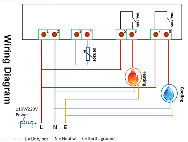
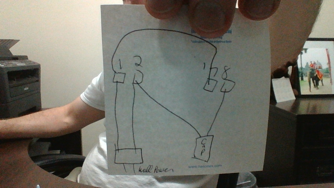
Stillshinen, That doesn't look right to me. Isn't one leg of the cap supposed to go to neutral and the other to line? If so, your drawing shows that you are applying neutral to both legs. I've attached the suggested wiring from the Ink-bird site. #1 is Line, #2 is neutral. I'd recommend jumping #1 to #7, then one leg of your cap going into #8. The other leg of the cap should go back to neutral (jump from #2.) Remember this is just a switch, so when the cool function is on, the switch between #7 & #8 is made.

20150708120436_92042.jpg
 
Stillshinen, That doesn't look right to me. Isn't one leg of the cap supposed to go to neutral and the other to line? If so, your drawing shows that you are applying neutral to both legs. I've attached the suggested wiring from the Ink-bird site. #1 is Line, #2 is neutral. I'd recommend jumping #1 to #7, then one leg of your cap going into #8. The other leg of the cap should go back to neutral (jump from #2.) Remember this is just a switch, so when the cool function is on, the switch between #7 & #8 is made.

RedLegEd,

So, if i am understanding you correctly the wiring should look like this?

Stillshinen

WIN_20151102_174319.JPG
 
Last edited by a moderator:
Not yet I will take a look and see it the video help considering I am wiring it to a three in on cap.


Sent from my iPad using Home Brew
 
So if I run separate wires from one and seven and connect them to the incoming power to one it looks like it will work. Any thoughts or an I missing something?


Sent from my iPad using Home Brew
 
Hi. Sorry it took so long to get back (been travelling.) Yes, now your diagram looks like it will work for the cool function. An easy way to check is to wire a receptacle (#8 black to gold and #2 white to silver) and plug a lamp into it. When the cool function switch is made, the receptacle should be "hot" (energized) and the lamp should go on.
 
I tested the set up with a light bulb as suggested and the diagram worked as intended, using a 2 prong lamp plug. I am trying to use the original cord for the freezer which is three pronged. The earth ground off the cord is screwed into the frame. Then off of the frame there are two more, one goes to the old thermostat and the other to the compressor. When I wire up that same way as the light, but switch light wires for Cap wires, the breaker trips every time i plug it in. The only difference was i used a 2 prong lamp type cord. Do i need to attach the earth ground to #8 as in the original diagram? I don't think that is right.

Would it be completely unsat to wire it to a 2 prong cord? I think so.

Any assistance is appreciated.
 
Do i need to attach the earth ground to #8 as in the original diagram? I don't think that is right.

Would it be completely unsat to wire it to a 2 prong cord? I think so.

Any assistance is appreciated.

Stillshinen,
No. Don't ground #8! That's the same as the line wire (black) from your source when the cool switch is made and you'll surely create a short circuit.

I'm not sure why the breaker is being tripped (unless it's a problem with how the output of the cap is wired.) I'm thinking the problem isn't so much with controller, but maybe with the refrigerator. Does the thermostat on the fridge still work? If so, I'd try replacing the cap (without the ITC-1000) to make sure everything works as originally designed.

If it does, then try to use the ITC-1000. Most folks wire an STC/ITC-1000 to a receptacle, then plug whatever (fridge, keezer, heat belt, etc.) into the controlled receptacle (that's where you run the ground from the 3-prong power from the wall socket.)

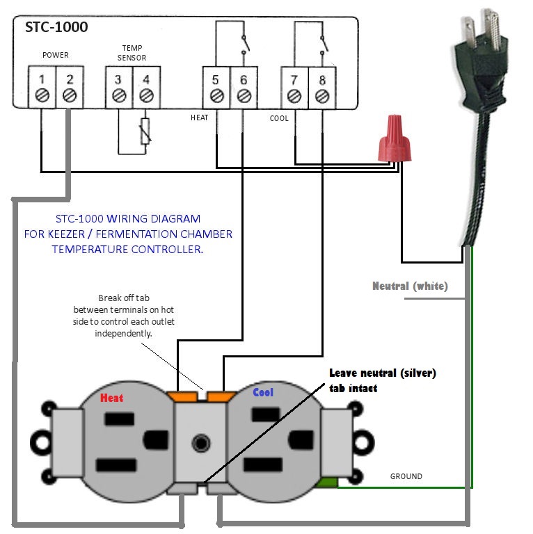
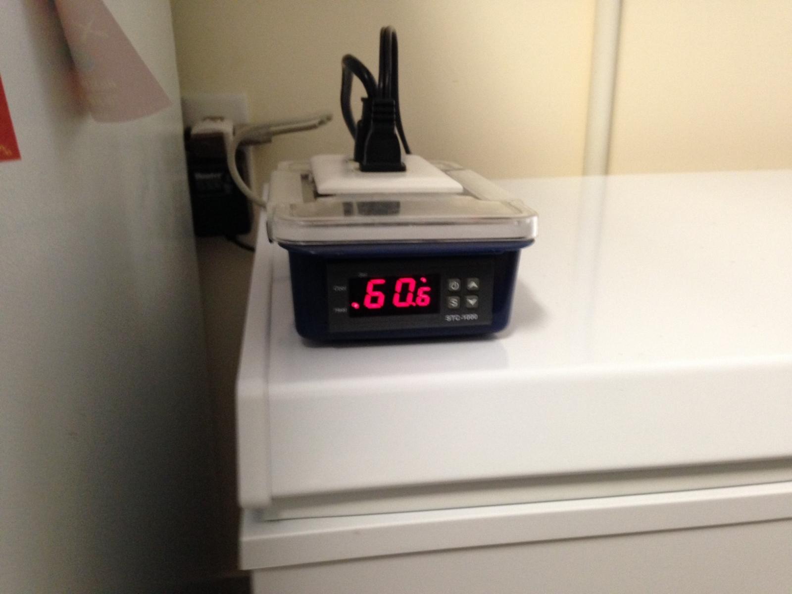
In any event, please be really careful and don't forget that the capacitor carries electrical potential even after it's disconnected from power and can/will deliver a shock. Here's how I wired my ITC-1000. Note how the ground goes to the controlled receptacle. I then plug whatever into the heat or cool side (as long as it's 10 Amps or less.) And what it looks like on my ferm chamber.

temp-controller-wiring-diagram.jpg


stc.jpg
 
Last edited:

Latest posts

Back
Top