HOWTO - Make a BrewPi Fermentation Controller For Cheap

Homebrew Talk - Beer, Wine, Mead, & Cider Brewing Discussion Forum

Help Support Homebrew Talk - Beer, Wine, Mead, & Cider Brewing Discussion Forum:

This site may earn a commission from merchant affiliate links, including eBay, Amazon, and others.
Status
Not open for further replies.
Damn this post is 4 years old now?!

Been out of country and dealing with new(ish) baby, so just now getting back into brewing and did my first batch in like 6 months this last weekend. Plugged trusty BrewPi back in and off it went, so that was nice.

Looks like there's been a lot of upgrades you guys are doing like the new webpage ill have to give a looksy at!
 
After several years, I've retired my Arduino legacy BrewPi and upgraded to the Spark.
BrewPi's setup documentation seems to have gotten no better. Does anyone know of a good setup description for the Spark that's as helpful as FuzzeWuzze's for the Arduino version?
 
Best as I can remember there have been no more than a handful of folks posting on HBT that even considered the BrewPi Spark, and only one or two that actually made that move. If you don't trawl up any takers here you might try pinging @doomy86 directly, or take a look at this thread https://www.homebrewtalk.com/forum/threads/brewpi-spark-diy-shield.524115/ for some other users that might have gone with the Spark solution...

Cheers!
 
If you only have 1 temperature sensor, it must be assigned as the "Fridge Sensor". BrewPi doesn't work with only a single sensor assigned as "beer sensor"

i have done the newest update and instaled revision C and I'm still unable to connect the temperature sensor to the rasp pi and get an output,. it detects the probe however when i set it for chamber temperature it keeps telling me nothing is connected, and im unable to assign it to ANYTHING that will give me an output.
 
i have done the newest update and instaled revision C and I'm still unable to connect the temperature sensor to the rasp pi and get an output,. it detects the probe however when i set it for chamber temperature it keeps telling me nothing is connected, and im unable to assign it to ANYTHING that will give me an output.
You indicate that you're connecting the sensor to your Pi. Is that really what you are doing, or are you connecting it to your Arduino?
 
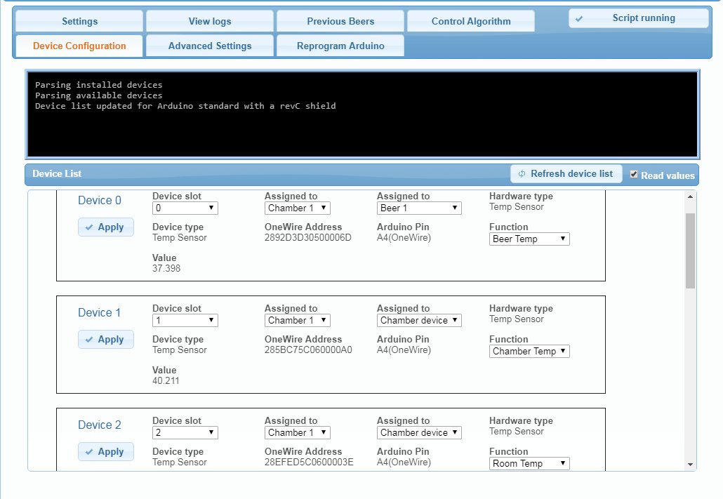
Assuming "detects the probe" means you've wired it where BrewPi is looking, perhaps this will help, it's the Device configuration panel with a full set of probes from one of my BrewPi minions.

brewpi_probe_setup.jpg


Note there are a few "switches" for each probe, and if you leave one set the wrong way it won't behave as expected...

Cheers!
 
Greetings, all. First and foremost, I want to thank FuzzeWuzze for his incredible hard work. Just amazing in its comprehensive nature and selfless in sharing. Thank you.

I have set up my fermenter as FuzzeWuzze has instructed - with the same parts as best I could source them - except that instead of using an outlet I hard-wired the aftermarket heater, the refrigerator's cooling unit, and the RPi off of the refrigerator's industrial plug (I was able to get a used $3500 Panasonic pharmaceutical fridge for $75. The amount of "excess" wiring and computer boards I had to remove was astounding).

Everything works perfectly except that the temperature sensors will fail and return a 'null' reading after some time in use. It doesn't seem to have a set schedule - its gone 10+ hours without issue until failure, and its gone only 2+ hours until failure. Only a sudo reboot of the RPi will solve the issue (though I will note that on reboot, the chamber/fridge sensor reports impossibly high temperatures. Like 180F type temperatures. The reading will then slowly but consistently lower until it reaches the actual temperature).

The log output for the most recent failure is as follows:

Aug 11 2018 07:53:01 Controller debug message: WARNING 2: Temperature sensor disconnected pin 18, address 28317CB816130179
Aug 11 2018 07:53:06 Controller debug message: INFO MESSAGE 0: Temp sensor connected on pin 18, address 28317CB816130179
Aug 11 2018 07:53:06 Controller debug message: WARNING 2: Temperature sensor disconnected pin 18, address 286642CC16130152
Aug 11 2018 07:53:31 Controller debug message: WARNING 2: Temperature sensor disconnected pin 18, address 28317CB816130179

Reading up on sensor issues over at the brewpi wiki leads me to believe it is a power issue. Maybe a faulty USB cord, maybe a faulty power cord for the RPi, maybe something else. I don't believe it is the electrical wiring itself because the heater, cooler, RPi don't report any power issues.

So before I go ripping apart my fermentor (I completely put the fridge back together. It looks stock except if you open the door), has anyone else experienced this problem? Thank you in advance!
 
If you are powering the Arduino from the RPi, that can often be a problem. Try powering the Arduino with its own 9 Vdc supply and see what happens...

Cheers!
 
If you are powering the Arduino from the RPi, that can often be a problem. Try powering the Arduino with its own 9 Vdc supply and see what happens...

Cheers!

So I went through my wiring again and noticed a *small* notch in one of the sensor wires that arguably exposed the wiring outside of it's rubber sheeth. I have rewired and will see how it goes.

However, if this did fix the problem thus implying the power to the Arduino is fine, would there be any harm in adding the 9v directly to the board anyway? Just curious .

Thank you!
 
No harm at all in supplying power directly to the Arduino even if that fixed your problem. As someone who chased power problems for a long time in my setup, low or unsteady power supplies cause all sorts of crazy errors like what you're experiencing.
 
A few years back (in this thread, I believe) I experimented with various 18" USB cables between an RPi and an Uno.
I found none of them provided a full 5V at the Uno, averaging around 4.75 volts, and some could barely break 4.5 volts. No bueno.
Skinny power/gnd wires make for voltage drop, the skinnier (and longer) the greater the drop.

All of my Unos have their own 9VDC @1A supplies...

Cheers!
 
So the next test eventually failed (with *fixed* sensor wires) so I went out and bought a 9v 600mA wall brick (I could not find a 9v 1A brick). This also failed so I have now replaced the connection from the Euro-style connector to 4A (18) as the log shows that the two sensors alternate as to which disconnects from pin 18, first.

We will see. Hopefully the 600mA vs 1A difference didn't scuttle my troubleshooting efforts. If wire-to-pin 18 replacement doesn't work I'd like to rule out all prior attempts and move on to replacing the sensors themselves (though I doubt they are they issue as they seem to alternate between failed states, equally).
 
Less than two hours later:

Aug 12 2018 09:31:58 Controller debug message: WARNING 2: Temperature sensor disconnected pin 18, address 28317CB816130179
Aug 12 2018 09:31:58 Controller debug message: WARNING 2: Temperature sensor disconnected pin 18, address 286642CC16130152

♂️
 
Ok, so did you wire in the 4.7K ohm resistor as shown?

Cheers!

Yes, sir.

Right now, I am investigating the possibility that my grounding scheme is messing up the sensors. Based on this link: https://community.brewpi.com/t/troubleshooting-temperature-sensors/14/16 I have grounded the sensors to the fridge metal itself and grounded the condenser and heater to the ground within the power cord (previously everything that had to be grounded was grounded - in one way or the other - to the fridge metal).
 
Nothing lasts forever. After about seven hours without the dreaded disconnect from pin 18, that's exactly what happened again .

Any thoughts on what I should check next? New sensors? Would the fact that the fridge sits on carpet be an issue? Maybe the Arduino is defective?

Ugg :(
 
just for giggles, if you can, try disconnecting the relay board. That will allow you to test the Arduino and the sensors by themselves. Who know, you may be getting some weird ground loop interference voodoo.
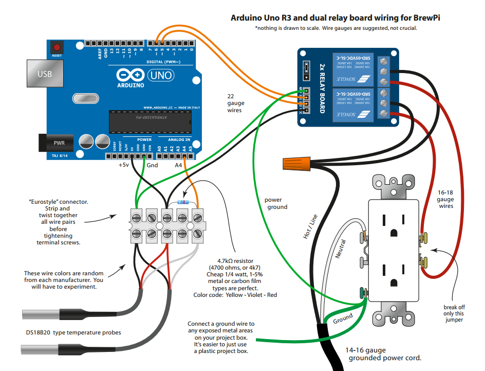
I also notice that between the two wire diagrams, that one ties the Arduino into the mains ground and the other doesn't. Is this an issue?

I noticed that too. I've tried multiple grounding schemes. I'm currently on ~12 hours no issues. The only change I made was I've place the eurostyle connector and arduino on a rubber mat. I'm think that if I rig a Faraday box and place both in there, I won't have issues any longer (seriously).
 
The Arduino, relay board (and Pi) should NOT be connected to earth ground. This is what's shown in Bigdaddyale's diagram. You need to remove the 'power ground' wire in Lord_BeerMeStrength's diagram. The ground for these low voltage DC circuits should be the same potential as the "return" for the DC output from the adapter. Earth ground is only for the AC safety and metal shields, not for intentionally passing current.

Trust me, in addition to being a homebrewer, I'm an electrical engineer who designs equipment like this for a living. It's not weird ground loop interference voodoo; it's predictable (if you know what you're doing).
 
The Arduino, relay board (and Pi) should NOT be connected to earth ground. This is what's shown in Bigdaddyale's diagram. You need to remove the 'power ground' wire in Lord_BeerMeStrength's diagram. The ground for these low voltage DC circuits should be the same potential as the "return" for the DC output from the adapter. Earth ground is only for the AC safety and metal shields, not for intentionally passing current.

As of Sunday, the sensors, relay and arduino haven't been grounded to earth, just metal (is that a problem?). The cooling unit and heater are grounded to earth.

Trust me, in addition to being a homebrewer, I'm an electrical engineer who designs equipment like this for a living. It's not weird ground loop interference voodoo; it's predictable (if you know what you're doing).

Well see, thats the problem; I only know how to follow instructions, I don't know what I am doing haha (though the fridge is never live when I work on it).
 
The Arduino, relay board (and Pi) should NOT be connected to earth ground. This is what's shown in Bigdaddyale's diagram. You need to remove the 'power ground' wire in Lord_BeerMeStrength's diagram. The ground for these low voltage DC circuits should be the same potential as the "return" for the DC output from the adapter. Earth ground is only for the AC safety and metal shields, not for intentionally passing current.

Trust me, in addition to being a homebrewer, I'm an electrical engineer who designs equipment like this for a living. It's not weird ground loop interference voodoo; it's predictable (if you know what you're doing).
What would be the recommended circuit?
 
What would be the recommended circuit?
The one you posted is recommended. Obviously, waall warts (AC/DC adapters) vary, but they should provide isolation between the AC input and DC output. Even if they somehow don't provide isolation, there's no ground loop, which is what leads to interference and failure or unreliable operation, unless a 2nd connection is made to earth ground or neutral.
In the diagram Lord_BeerMeStrength posted, the earth ground connection by itself might not be a problem. The problem arises when the DC power via adapter or USB also provides a ground path.
 
In the 'Bigdaddyale' diagram they are grounding a metal case that the powersupply might be placed in ( if not using a wall wort.) For your transformer just ignore the grounding wire from the Mains to the grounded shield.
Ignore the shoddy MS paint.
 

Attachments

  • wiring-diag.gif
    wiring-diag.gif
    120.7 KB · Views: 94
Wanted to thank everyone for their help. Its been almost four days without issue. I believe the big thing - in my case - was proper grounding. I found it is important to keep the sensor and arduino ground separate and not earth ground.

Happy brewing!
 
Wanted to thank everyone for their help. Its been almost four days without issue. I believe the big thing - in my case - was proper grounding. I found it is important to keep the sensor and arduino ground separate and not earth ground.

Happy brewing!

So with everything working, I foolishly tried to put the fridge "back together" (i.e. place the wires in their final position, move the parts from outside the case to inside the case, general clean-up - POWER OFF THE WHOLE TIME) and, wouldn't you know it, the sensors stopped working! So I checked all the wires - replaced the wires that appeared suspect - and ultimately replaced the sensors and .... they heated up until they were too hot to touch and stopped working.

*sigh*

Its a good thing I love beer, brewing beer, and fooling around with linux and electronics otherwise I might have quit a long time ago.
 
Reversed voltage/gnd at the ds18b20s will do that (bt/dt - once - sending that probe to an early grave).
Sorry...

I understand that but unless the color of the wires differs from one sensor to the next - from the same manufacturer, packaged together - they are wired correctly.

I've decided to order new sensors and the required parts to utilize mini-xlr connectors in hopes of making my job easier when in the future the sensors fail again
 
There has been some variance in the wire colors in the past. Whether it was within the same manufacturer, I can't say.

Regardless of wire color, if it got hot it wasn't wired properly. While I've gotten lucky in the past, usually it kills the sensor and it's recommended to replace it once it heats up like that.

ETA: I bring this up only to recommend that you double check the wiring so that you don't do the same to any new sensors.
 
Last edited:
There has been some variance in the wire colors in the past. Whether it was within the same manufacturer, I can't say.

Regardless of wire color, if it got hot it wasn't wired properly. While I've gotten lucky in the past, usually it kills the sensor and it's recommended to replace it once it heats up like that.

ETA: I bring this up only to recommend that you double check the wiring so that you don't do the same to any new sensors.

Any way to test the sensors other than trial and error? They aren't terribly expensive but if I'm buying bag after bag of sensors the whole build gets silly
 
Any way to test the sensors other than trial and error? They aren't terribly expensive but if I'm buying bag after bag of sensors the whole build gets silly

There was some talk in this thread about how to test them to determine the wiring. Which sensors are you buying? Have you posted any pictures of your current setup?
 
Strange, they both have the same wiring scheme listed. I would use your arduino and a test sketch to test them prior to installing them permanently. I would also check (and re-check) your wiring.

Maybe even post a picture of it here so we can have a look.

When I've heated one up in the past, I've been able to re-wire it and use it. Sometimes, it was within 1/2 a degree of a known good sensor. So it's possible it's still good.
 
Status
Not open for further replies.
Back
Top