How do you run 240V on single leg for 120V PID control

Homebrew Talk - Beer, Wine, Mead, & Cider Brewing Discussion Forum

Help Support Homebrew Talk - Beer, Wine, Mead, & Cider Brewing Discussion Forum:

This site may earn a commission from merchant affiliate links, including eBay, Amazon, and others.

riverbeer

Well-Known Member
Joined
May 2, 2013
Messages
54
Reaction score
1
Location
Carolina Lowcountry
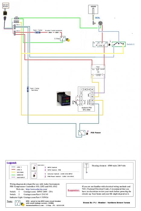
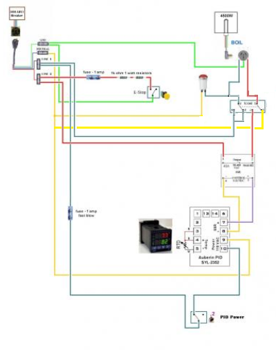
Been running my temp control using PJ diagram. I want to be able to run my element at 1/2 power, so I put a switch to the other line thinking I could turn off switch 2 and have the PID run the element on 120V. (2nd pic)
Apparently it doesn't work that way, why not ?
Is there simple way to wire this so I can have both switches on for full power or 1 switch on for PID to run at 120V ?
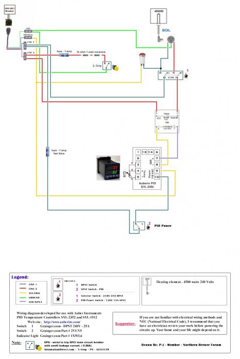
Auberin-wiring1-a4-4500w-BIAB-30d.jpg


2 Switch wiring.jpg
 
Killing one leg of 240 interrupts the circuit. You have to replace the one leg of 240V you kill with a neutral to get 120V. I cannot read the diagrams very well but I think if your switch were a SPDT like this:

325px-SPDT-Switch.svg.png


With COM going to your element, L1 your 240V leg and L2 neutral you would be on the right track.
 
to run a 240 element on 120 you need to have a neutral connected to one side of the element

it will not work with just one hot leg, also it will be much less then half power

there is a formula out there but I believe it is about 25 % of the wattage when ran on 120

all the best

S_M
 
I'm having trouble getting this into my head.
I can power off the PID and the pot still boils unless I power off the element switch. The element is still getting power from somewhere without a neutral connected. Is it feeding back thru the ground?
 
I'm having trouble getting this into my head.
I can power off the PID and the pot still boils unless I power off the element switch. The element is still getting power from somewhere without a neutral connected. Is it feeding back thru the ground?

Are you asking a question, or stating that if you turn off the PID power switch the element is still powered? If that is the case it is likely that your SSR is toast and not controlling the element (it has failed closed) and you need to get a new one.

To do what you want with the gear you have you need to, as lschiavo, says change the wiring on SW1 so that the commons run to the element. The on one pole both termninals have L1 wired to them (the common of this has the indicator light wire back to nuetral), the other pole one terminal has to L2 and the other has nuetral.

Lathough this way you don't have a off switch for your element

new.png
 
Are you asking a question, or stating that if you turn off the PID power switch the element is still powered? If that is the case it is likely that your SSR is toast and not controlling the element (it has failed closed) and you need to get a new one.

To do what you want with the gear you have you need to, as lschiavo, says change the wiring on SW1 so that the commons run to the element. The on one pole both termninals have L1 wired to them (the common of this has the indicator light wire back to nuetral), the other pole one terminal has to L2 and the other has nuetral.

You bring up a good point. Thank you. Maybe my SSR is fried, When I power off PID ,my pot is still boiling.
Can I disconnect power and do a continuity test on SSR to check for closed circuit? If there's continuity with power off ,it's fried, is that correct?
 
You bring up a good point. Thank you. Maybe my SSR is fried, When I power off PID ,my pot is still boiling.
Can I disconnect power and do a continuity test on SSR to check for closed circuit? If there's continuity with power off ,it's fried, is that correct?

I dont think you can simply do a continuity test. Basically if you disconnect the control leads and it still lets power through then it is no good. Also just double check you do not have a SSVR which is a completely different beast that looks identical :D
 
Yes sir, my SSR is cooked. 0 resistance at output.
Thank you, Mattd2 for spotting that. I never would have thought of that.
This SSR is pretty new.
I've checked my wiring and it looks like it's supposed to.
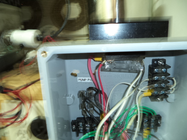
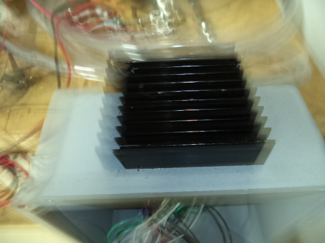
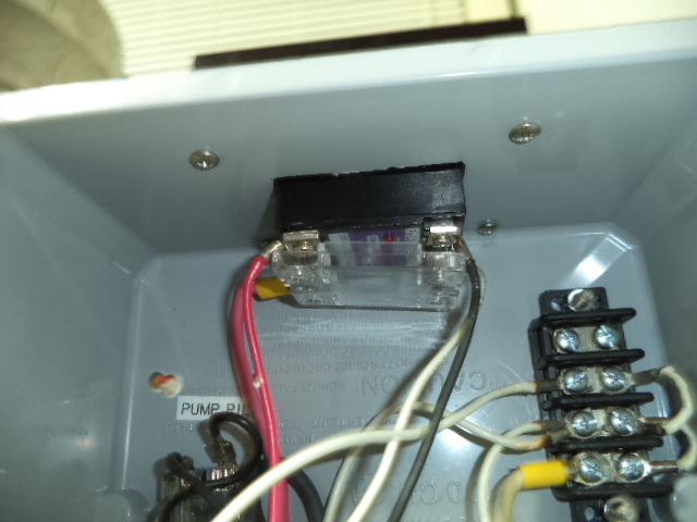
Here's some pics of my box, anybody see any reason the SSR cooked.

DSC00154.JPG


DSC00155.JPG


DSC00156.JPG
 
If you really do have a double pole double throw switch as shown in the first diagram, I'd be very cautious and double check that you are connected to the correct terminals. To test if the SSR is working properly, just direct wire (temporarily) L1 to the element and L2 through the SSR and to the element. That eliminates any switch wiring errors for now. Also, can you link to the exact switch that you bought for that piece in the diagram?
 
Back
Top