Help with Schematics for Herms electric BCS 460 2 element brewing system

Homebrew Talk - Beer, Wine, Mead, & Cider Brewing Discussion Forum

Help Support Homebrew Talk - Beer, Wine, Mead, & Cider Brewing Discussion Forum:

This site may earn a commission from merchant affiliate links, including eBay, Amazon, and others.
I've seen where people mount a plug inside for the 5V walwort. That's probably the easiest, I was looking for an AC to DC converter board that would accept 110V - didn't find one in the few minutes I looked on e-bay, but something like that would work as well if you can find it.

Could i just leave the BCS plug on the inside and run wires from the terminal blocks right onto the plug itself and just make sure i put some heat shrink or electric tape over it to cover the exposed wire?


Also - i just realized, how do you mount the BCS internally? It is just a black square, no mounting brackets came with mine.
 
Have you considered a computer power supply which will give you 12volts which you can tune down to 5........
 
Have you considered a computer power supply which will give you 12volts which you can tune down to 5........

I had not, my box is getting a little crowded, hoping not to have add something like that.

I was thinking that running another line from the terminal block... into another 5A fuse and then into a power recepticle would do the trick. Anyone have any reason why that would not work?


Still building but I do have a question. Is there any reason why switch 7 doesn't have power connected to the illumination?
 
Still building but I do have a question. Is there any reason why switch 7 doesn't have power connected to the illumination?
Yes. The circuit required to power the switch light is fairly complex and indeed would need to have more N/O modules added to it for it to function. The indicator lamps on switches 5 & 6 will tell you which function has been selected (HLT or BOIL).
 
Yes. The circuit required to power the switch light is fairly complex and indeed would need to have more N/O modules added to it for it to function. The indicator lamps on switches 5 & 6 will tell you which function has been selected (HLT or BOIL).

If I just wanted to keep that switch lit all the time, can i just hook in power and run a line to neutral?
 
If I just wanted to keep that switch lit all the time, can i just hook in power and run a line to neutral?
You could do that by setting up switch 7 with the same configuration as switch 2.
Terminal 5 would be power input and terminals 4 & 6 would be jumpered and connected to one side of the indicator light. The other side of the indicator light then goes to neutral. This way the indicator light will only be on when the switch is selecting. The light will be off in the center off position.

Hope this helps.

It sure does... as always P-J... you are the man.


So... I finished the panel and flipped on the BCS and everything seems to be working nicely except for the two SSRs connected to the heating elements.

I have the panel wired exactly like the above schematic with one exception, i hooked the ground from the BCS to the system ground terminal block. (per a prior recommendation)

With it wired that way, the two SSRs hooked up to the heating elements appear to be on all the time (little SSR LED light is on).

However, if i remove the wire from the BCS to the system ground, the SSR lights switch off. Even with the system turned off, but only the BCS on, the SSR LED's are still on.

Since i don't have heating elements yet, I haven't been able to confirm if those two outlets are actually receiving power, but since the SSR light is lit, i assume it has activated the SSR.

Any insight as to why this is happening, and do i really need to ground the BCS to the ground terminal block?
 
Connecting BCS ground to the panel ground shouldn't have any effect on those SSR unless something else isn't wired properly.
That said, no you don't have to wire the panel ground to BCS ground, but I saw my temps doing some pretty large fluctuations until I did that.

Switches 5 and 6 are in the position to pass OUT0 and OUT1 I presume (not VDD +5)?
 
This is a common thing people see and post about. SSR do tend to leak voltage, even when they are off, if you hook a multimeter up to them it will give you a reading, usually less than the voltage you are trying to control.

This problem tends to go away after the SSR are turned on controlling a load. Not sure what the reasoning is behind this is, but SSR are not mechanical relays. If it does not you could have two bad relays, but I don't think that is too common.

When I first tested my panel all the lights where on, even though every thing was off according to the BCS. Once I hooked all the elements and pumps up and did a wet run all the lights where off when off and on when on after the wet run.
 
Thanks Bruin and Bsquared... I have checked, double checked and triple checked, I can't see where i made an error in wiring. It just flat out didn't make any sense to me because even when the switches were in the center (off) position, somehow it was still illuminating the SSR.

Bsquared - that is excellent info... so essentially, after i hook up the heating elements, it should fix the problem?

I did test the pump outlets with a light, since they are standard outlets, but until i order the heating elements, ill just have to wait to test the heating elements.
 
My SSR lights don't require a load to work properly.. the lamps after the SSR illuminate when there's no load due to the leaked current, but the SSR indicator is still off.
Try testing the pump SSR without a load and see if it behaves the same...
 
Hopefully yes, putting the SSR under load should stop the lights from being on when they should be off.

Bsquared - side question in regards to this build... I am assembling all the valves and what not for the kettles....

so I was doing some research on sight gauges as well as thermometers for back up temp monitoring for my 3 new SS 80qt kettles and i stumbled upon the brewhardware site glass and temp probes and noticed that you had commented on them while putting together your setup.

Did you end up buying them?.... I am leaning torwards buying 1 of the sight glass temp gauge combo for each kettle.... what do you think of the ones you have? Have they been pretty durable? Does the glass change color over time with the hot wort? and any other info.

Thanks!
 
I am going to get this going again... i am nearing completion... however i am still having problems with the SSRs turning off... and i think i found the problem...

What is the difference between the Red and the green switch options for the switches?
 
One is NO (normally open) the other is NC (Normally Closed) this means when the switch is off the contacts are open in NO and closed in NC

Does that make sense?
 
How about the resistor... where do you find it and how do you include it in the setup?


So... I finished the panel and flipped on the BCS and everything seems to be working nicely except for the two SSRs connected to the heating elements.

I have the panel wired exactly like the above schematic with one exception, i hooked the ground from the BCS to the system ground terminal block. (per a prior recommendation)

With it wired that way, the two SSRs hooked up to the heating elements appear to be on all the time (little SSR LED light is on).

However, if i remove the wire from the BCS to the system ground, the SSR lights switch off. Even with the system turned off, but only the BCS on, the SSR LED's are still on.

Since i don't have heating elements yet, I haven't been able to confirm if those two outlets are actually receiving power, but since the SSR light is lit, i assume it has activated the SSR.

Any insight as to why this is happening, and do i really need to ground the BCS to the ground terminal block?

I am planning very similar build and just wanted to confirm that lines feeding switch 7 and ultimately the coil do not need to be 10AWG. Since it has a 5a fuse upstream it would seem 12 or 14 would be fine... Correct?
 
Tom_FL said:
I am planning very similar build and just wanted to confirm that lines feeding switch 7 and ultimately the coil do not need to be 10AWG. Since it has a 5a fuse upstream it would seem 12 or 14 would be fine... Correct?

That is correct... Since it is only powering the coil. I used 14awg but you'd be ok up to 16 or 18 gauge ... I just brewed my first batch on my completed system and it works perfectly... Just need to put some finishing touches on the panel (labels and touch up paint... All cosmetic)... I will post some pictures sometime this week and post a price sheet for what i spent. The guys on this thread helped me tremendously. Thanks goes to them.
 
The plan is to plug in using an unused drying outlet in my house that is about 15 feet from the brewing location, I assumed it would be too much power required to run both elements and both pumps at once.

Here is the sequence:
1. Heat Strike Water in HLT
2. Transfer Strike water to MLT
3. Re-Fill HLT to cover HERMS coils as well as reach sparge water quantity
4. Heat HLT to Strike Temp while running both pumps to circulate both HLT water (to maintain temp evenly) and circulate MLT threw herms coils to maintain Temp
5. Mash in - increase or decreasing temp in HLT as necessary (should be held constant by BCS 460)
6. Increase temp of Mash by increasing HLT water to mash out temp
7. Sparge - 2 pumps running - 1 to pump sparge water to mash out and 1 to pump out wort from beneath a false bottom in the MLT
8. Switch heating elements to raise BK to boil
9. Pump from BK through Plate chiller into fermenter


So at any given time, I'll need 1 element and both pumps going at once. Let me know if more detail is required.

Your process sounds good to me. I have used my eHERMS once (last weekend) and did it a bit different... considered this process but tried to heat exchange heat all my mash water... it was taking too long so I wound up overheating my HLT water and having to cut it with cold water to bring it back down for re circulation.
 
BrewskiBroski said:
That is correct... Since it is only powering the coil. I used 14awg but you'd be ok up to 16 or 18 gauge ... I just brewed my first batch on my completed system and it works perfectly... Just need to put some finishing touches on the panel (labels and touch up paint... All cosmetic)... I will post some pictures sometime this week and post a price sheet for what i spent. The guys on this thread helped me tremendously. Thanks goes to them.

Thanks. Any other changes our decided to go with from what is drawn?
 
Thanks. Any other changes our decided to go with from what is drawn?

I did make a couple little changes. I did add a power to the illumination on the 7 switch, so that it is lit when the power is on, which is just a branch off of 2 to the illumination connector on that switch.

Per some previous conversations, I did wire the BCS ground to the system ground.

Outside of that, I wired it identical to the schematic.
 
I was going to go without any lights. Do you find them necessary? If so which circuits. The 3-way switches I ordered do not have ili,Marion but I could easily add in a few LEDs.

Thanks
 
I was going to go without any lights. Do you find them necessary? If so which circuits. The 3-way switches I ordered do not have ili,Marion but I could easily add in a few LEDs.

Thanks

I would not say that they are necessary. However, it is definitely a nice reminder that something is still on, particularly the heating elements, since you don't want to dry fire them by accident.
 
Anyone have any inbox pictures? I'm having some major brew stand issues with the stand I had built and I'm converting my HLT and BK to 5500W elements. I have a BCS and a bunch of 120v gear in another box so I'm going to order a second box and seperate out the 240v equipment but, run connections back to the BCS for control from one box to the other. Everything 240v self contained. I'm going to go with Kal's setup 100% on the heating element setup. I see high gravity brewing has elements but, they look a bit "less" protected to my eye when I can piece the components out and work up Kals for $20 more.

Rich
 
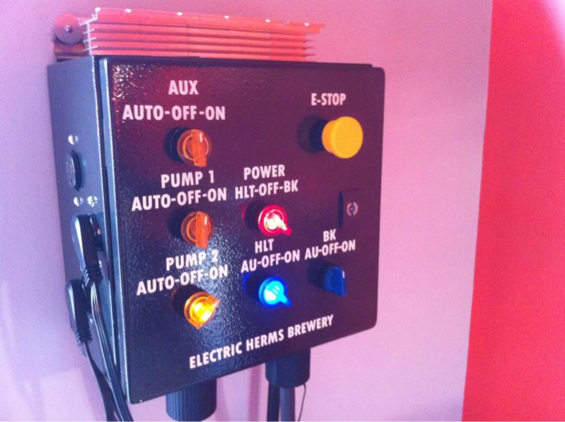
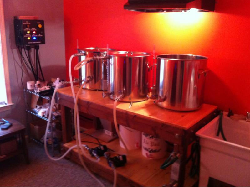
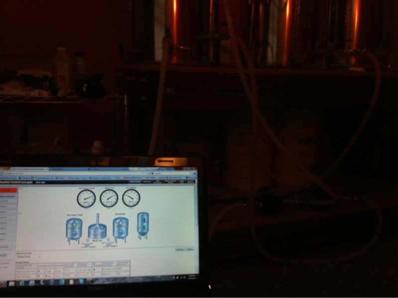
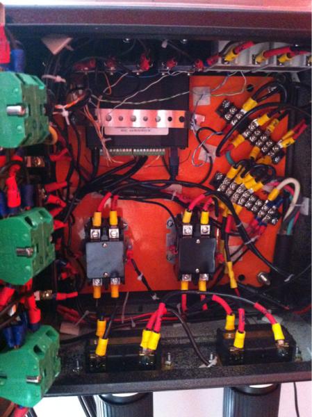
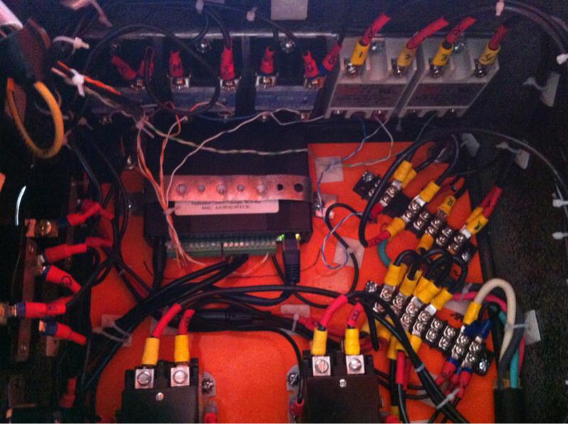
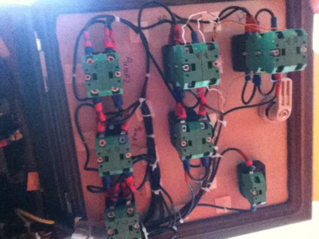
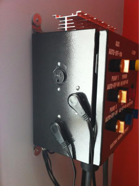
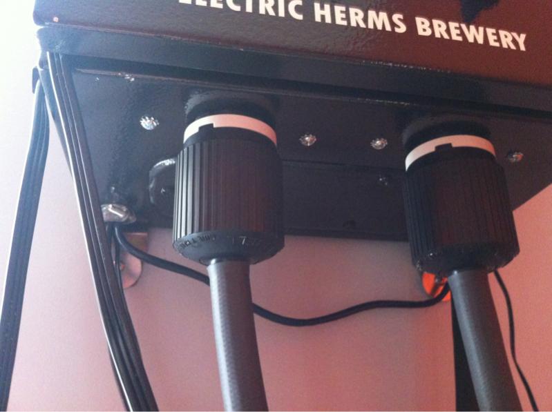
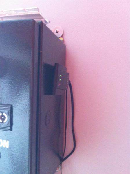
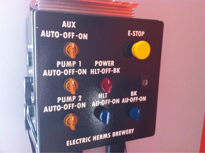
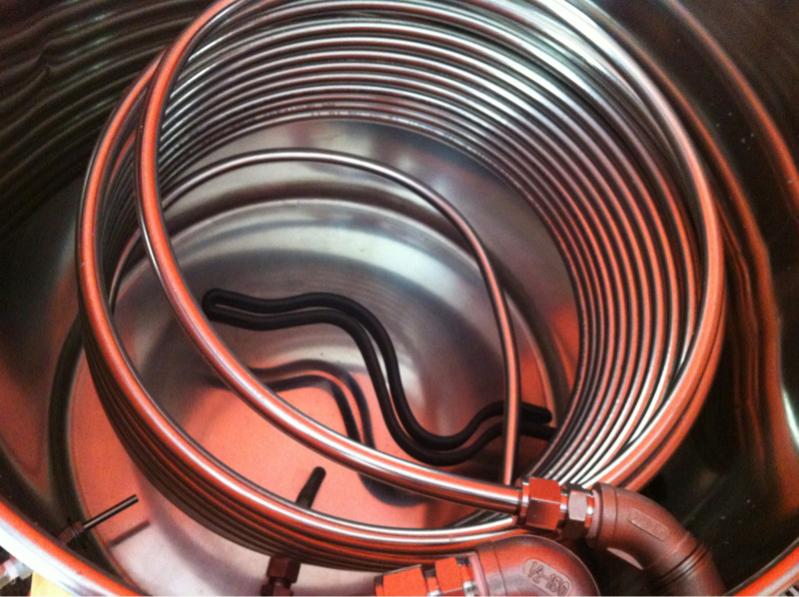
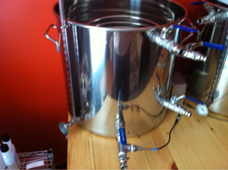
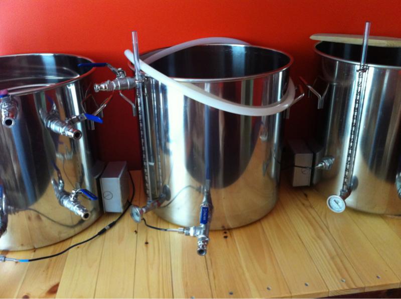
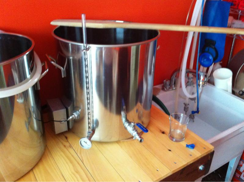
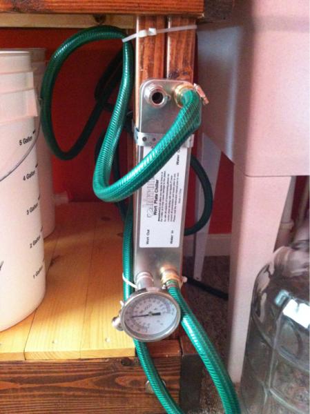
Here are some pictures of my setup... I am not an electrician or an electrical engineer, I just researched the hell out of the project on here and various electric google searches. P-j helped out big time with the schematic and several others helped tremendously by answering all my questions. Took about 3 months. I will post a price spread sheet later but I think it cost around 3k (got a nice bonus in feb).... That price includes the sink that I plumbed, the table that I built, the vent, paint for the room and various other items like a chiller and pumps that I already had from prior upgrades. Total panel cost was prob between 800-1000 and a lot of hours building. Again, i will post an expense spreadsheet with all the details. My first beer is fermenting like crazy now. Thanks everyone for the help in building this... I hope this thread provides help for others.

image-2164658870.jpg


image-2350125996.jpg


image-3063122867.jpg
 
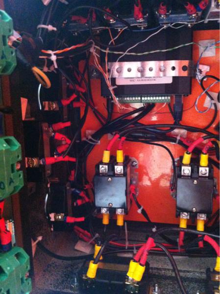
Brewski, I'm curious if you have programmed your bcs? And if you might share it? Also if possible an inside shot of your panel?
 
Quick question... I've ordered all the components to make something similar to this happen (Thanks everyone in the thread!)

How did everyone handle the fuse situation? I'm a bit confused how you take a 30amp leg off the terminal strip and hook a 5amp fuse up to it before the first switch? How does that fuse not blow? How do you wire it, inline fuse holder, or ???


EDIT:
Scratch that, page 4 answered my question, I've read every darn line, eyes are just starting to glaze over! This should be fun... Is there any easy way to attach the resisters without soldering? That's all I have! Photo's of the build to come!
 
I just used a little clamp connector from homedepot and put heat shrink over that ... Very simple and protected
 
I just used a little clamp connector from homedepot and put heat shrink over that ... Very simple and protected

Any chance you can take a photo? (Not great with electronics!) I saw page 5 with the solder comments, I'm trying to avoid that at all cost! Or is it just an electrical union? Did you solder to the fuse holders or use something else for that?

Thanks BTW! :mug:
 
Beeskneesbrew said:
Brewski, I'm curious if you have programmed your bcs? And if you might share it? Also if possible an inside shot of your panel?

There wasn't much programming at all... I got the temp sensors from brewershardware.com and Darrin (the owner) has the calibration coefficients listed on his website... I had to tweak a little to really tune them in... But it was relatively easy... That was the extent of it... I have only used in manual mode so far... Which is just set temps on the computer and it will fire the elements as needed to maintain those temps... I will eventually setup some processes so it just runs on its own for certain sections of brewing... But again the layout and user interface of the bcs system is very user friendly. I am a little tech savy but definitely not a programmer or computer engineer and was able to get it going.

I listed some more pictures of the panel as requested... Let me know if there is something that you want me to zoom in on.

image-4142411108.jpg


image-1440659851.jpg


image-4254211324.jpg


image-2186216467.jpg


image-1246628109.jpg


image-244532410.jpg


image-4157023815.jpg


image-2361877024.jpg


image-3633739813.jpg


image-2890023185.jpg


image-1893330819.jpg


image-1216678815.jpg


image-1875286689.jpg


image-876185877.jpg
 
The only thing I'm not looking forward to is buying the punch to put the holes in the kettle. I'd try to use a step bit but, I keep seeing horror stories.
 
horric29 said:
Any chance you can take a photo? (Not great with electronics!) I saw page 5 with the solder comments, I'm trying to avoid that at all cost! Or is it just an electrical union? Did you solder to the fuse holders or use something else for that?

Thanks BTW! :mug:

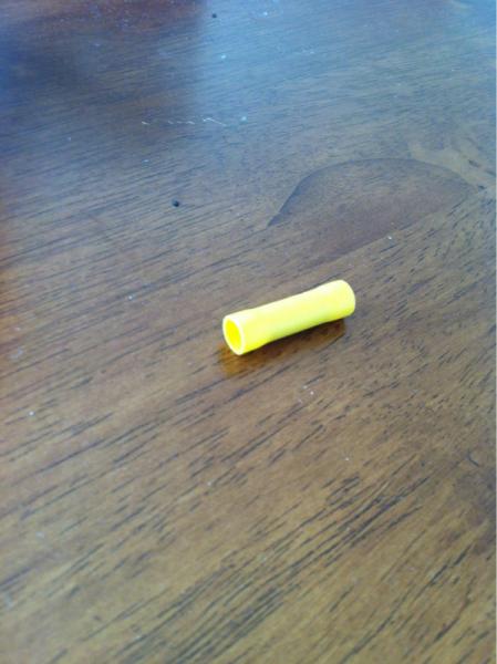
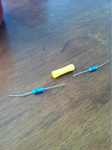
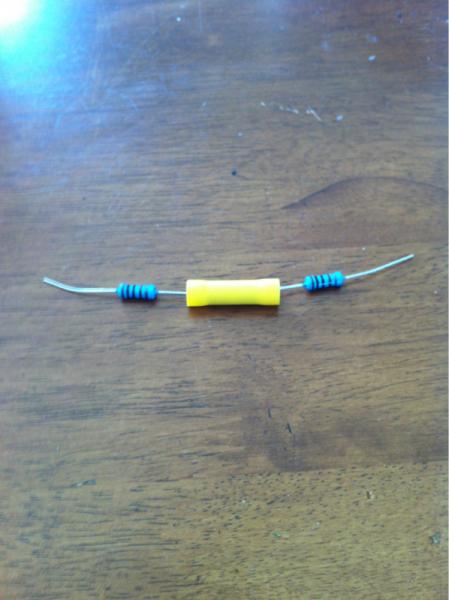
Sure... Now... I couldn't get a good pic of it in the panel because it is kind of tucked behind the bcs... But here is an example (the yellow connector is far bigger than needed ... rated for 10gauge wire.. This just for the example)... Once you have the resisters in... Use a wire stripper/clamp tool to clamp them and secure them .. You would also need one of those connectors on either side to connect it to the wires too... Then I used heat shrink around the entire thing to protect it more.

image-1011097805.jpg


image-1434955333.jpg


image-885299047.jpg
 
horric29 said:
Any chance you can take a photo? (Not great with electronics!) I saw page 5 with the solder comments, I'm trying to avoid that at all cost! Or is it just an electrical union? Did you solder to the fuse holders or use something else for that?

Thanks BTW! :mug:

Also... I used the same method for connecting in line fuses... I didn't do panel mounted fuses... Waist of time to drill more holes in the panel ( btw used the cheap ass step bits from harbor freight for all of the holes in both the panel and the kettles... Worked perfect... Just go slow and use vegetable oil... Might have to do a starter hole on the kettles first tho and have a metal file to round off the edges)
 
Also... I used the same method for connecting in line fuses... I didn't do panel mounted fuses... Waist of time to drill more holes in the panel ( btw used the cheap ass step bits from harbor freight for all of the holes in both the panel and the kettles... Worked perfect... Just go slow and use vegetable oil... Might have to do a starter hole on the kettles first tho and have a metal file to round off the edges)

Hmmm... If it worked for you, I think I'll give it a shot. The step bit is dirt cheap at HD, I'm sure I'll never use it again either...
 
This might help too... this is the entire expense breakdown for all of the brewery, as well as where I purchased equipment. This includes everything... including paint for my room/plumbing/the stand) I did a lot of research and this is as cheap as i could get it. Some things i did purchase assembled... like the heating elements (from Kal)... wasn't much of an expense save to build myself. Should be pretty accurate though. I attached it.
 
This might help too... this is the entire expense breakdown for all of the brewery, as well as where I purchased equipment. This includes everything... including paint for my room/plumbing/the stand) I did a lot of research and this is as cheap as i could get it. Some things i did purchase assembled... like the heating elements (from Kal)... wasn't much of an expense save to build myself. Should be pretty accurate though. I attached it.

Hmmph. Don't see it here. No worries though, I already purchased everything. I thought the same thing about purchasing the elements from Kal but, decided to go on the adventure myself... I'll have to post my writeup.

I started another thread and nobody replied but, I bought a bum gas stand that was supposed to have automated gas for the burners. Decided after all the problems to just convert to electric and I already have the BCS, pump control, etc through another box, just going to build a seperate box for the 240v stuff and just run a piece of CAT6 to the other box for DC & BCS control of the burners...

It would have been a hell of alot quicker to just strart out going electric following this setup.... Live and learn!
 
Back
Top