Help! Temp sensor connection to PID?

Homebrew Talk - Beer, Wine, Mead, & Cider Brewing Discussion Forum

Help Support Homebrew Talk - Beer, Wine, Mead, & Cider Brewing Discussion Forum:

This site may earn a commission from merchant affiliate links, including eBay, Amazon, and others.

IndyBlueprints

Well-Known Member
Joined
Oct 30, 2010
Messages
140
Reaction score
54
Location
Indy
I have a wiring diagram for a thermocouple connecting to a PID, and it shows two wires coming off the thermocouple connecting to "TC+" and "TC-". However, I have a PT100-L50NPT temp sensor, and it has three wires, two red and one white. Any idea where the third connection goes, and which wires connect where?

Thanks,

Allen

A PT100 is a totally different type of sensor than a thermocouple. Some PID's will work with either (need to have parameters set correctly in the PID based on type of sensor), some may work only with thermocouples, some may work only with PT100 sensors, and some may only work with other types of sensors. What model PID do you have?

Brew on :mug:
 
I'm sure they are compatible, as I got them together from Auber Instruments. The sales rep with Auber suggested them together, knowing my application was a RIMS tube.

The PID is a "SYL-2352", 1/16 DIN PID temp controller.
 
I'm sure they are compatible, as I got them together from Auber Instruments. The sales rep with Auber suggested them together, knowing my application was a RIMS tube.

The PID is a "SYL-2352", 1/16 DIN PID temp controller.

Ok, You're good. The SYL-2352 can use many different types of temperature sensors. You can find the manual for the SYL-2352 here: http://auberins.com/images/Manual/SYL-2352_manual.pdf. The temp probe you have is an RTD, and is connected as shown in the pic below.

RTD Connection to SYL-2352.png

Brew on :mug:
 
Your answer is here:
<http://auberins.com/images/Manual/SYL-2352_manual.pdf>

"3.1.2 RTD sensor
For a three-wire RTD with standard DIN color code, the two red wires should be connected to the terminals 3 and 4. The white wire should be connected to terminal 5."
 
So, my next question;

I am using the PID to control the water heating element. I am putting a toggle switch and indicator light in between the PID and the SSR. The reason is, I would like to be able to tun on the PID and get the pump circulating before I actually let the element turn on. No issues there.

My issue is I have a total of 3 toggle switches; One to turn on the pump, and one to turn on the power to the PID. The toggle switches I have are "ts1 3-pin toggle switches". The are rated for 5A @ 120VAC. Although I assume they will be fine between the PID and the SSR, I doubt they are rated high enough for the main power or the power going to the pump. (Sorry, my training is in carpentry, not electricity).

Will these switches work for any or all of the 3 applications, or do I need to get something stronger?

Thanks,

Allen

You really want a switch that positively disconnects the power from the element. SSR's usually fail in the on state, meaning they shouldn't be depended on to provide a positive disconnect in all cases. Also, SSR's have enough current leakage to give you a good shock when off, even when they are working correctly. The disconnect for the element power needs to be double pole so that it switched both hot legs, as switching only one leg is a safety hazard. You can use a contactor (high current relay) or a mechanical switch. Probably the simplest option is to use a Leviton 3032 series (or equivalent) double pole, single throw toggle switch (looks like an ordinary light switch, but handles more current.)

Do you have a design drawing for the control panel that you are building? This is not the kind of project you want to improvise along the way, especially if you don't have an electrical background. If you have a drawing, post it here, and some of the more experienced folks can review it for functionality and safety. If you don't have one, post exactly what features you want in your control panel, and how it should operate. There are folks here who can help you with designs.

Brew on :mug:
 
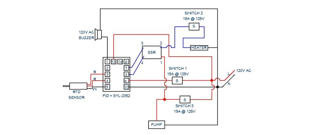
This is what I'm thinking currently. Does it look like I'm on the right track?

PID%20PROPOSED%206.jpg

My previous response assumed you were planning a 240V system with 4500W or 5500W heating element. Your design is obviously for 120V, so you can use single pole switches. The important question: what is the wattage rating of your heating element @ 120V? If it is more than 1500W, then you should use 20A rated switches, except for the PID power switch.

Brew on :mug:
 
Yes Sir.

I'm running a 5,500W 240V heating element wired at 120. So, an effective rating of 1,375W at 120 gives it about 11.4A, so i'm going with 15A switches.

Am I right in thinking that the only switch that needs to be 15A is the one between the SSR and the Heating element?
What about the switch going from the pump to the SSR?

Switch 2 will carry max 11.4A so 15A rating is ok. Switch 3 will carry 11.4A plus the pump current, including the motor start surge. I recommend higher than 15A rating for Switch 3. Switch 1 will carry less than 1A.

Brew on :mug:
 
Switch 2 will carry max 11.4A so 15A rating is ok. Switch 3 will carry 11.4A plus the pump current, including the motor start surge. I recommend higher than 15A rating for Switch 3. Switch 1 will carry less than 1A.

Brew on :mug:

The Chugger pump is only 1.4A, so added to the 11.4A heater is 12.8A combined. I should still be OK at a 15A switch.
 
The Chugger pump is only 1.4A, so added to the 11.4A heater is 12.8A combined. I should still be OK at a 15A switch.

I'm not a motor expert, but I do know that inductive loads have higher turn-on currents than their steady state currents. A motor is an inductive load. Some panel designs recommend using slo-blo fuses in the motor branch of the circuit due to the higher start-up currents. It's possible that the higher in-rush currents could adversely affect the reliability of marginally rated switch contacts. But it is also possible that a 15A switch could work for years in your circuit design. Personally, I'd use a higher rated switch.

https://en.wikipedia.org/wiki/Inrush_current:
"Inrush current, input surge current or switch-on surge is the maximum, instantaneous input current drawn by an electrical device when first turned on. Alternating current electric motors and transformers may draw several times their normal full-load current when first energized, for a few cycles of the input waveform."​

Brew on :mug:
I don't know what most of that means. But it's easy for me to switch out that 15A switch with a 20A switch. In Stock items at Lowes.
 
Back
Top