Help controlling motorized ball valves

Homebrew Talk - Beer, Wine, Mead, & Cider Brewing Discussion Forum

Help Support Homebrew Talk - Beer, Wine, Mead, & Cider Brewing Discussion Forum:

This site may earn a commission from merchant affiliate links, including eBay, Amazon, and others.

planker101

Well-Known Member
Joined
Aug 23, 2010
Messages
212
Reaction score
39
Location
Reno
I literally spent the last 5 hours searching the internet and this site to tey and figure this out, but clearly I don't even know enough to know what to search for.

I got a bunch of motorized ball valves in a lot of brew fittings and would like to incorporate them into my system. Unfortunately I have zero experience going from AC to DC power. (I have done plenty of wiring in my house, but that is pretty straight forward).

If someone is willing to give me a walk through from my house outlet to the ball valve I would be extremly appreciative! I would like to build a control box that will allow me to control up to 8 ball valves. Two of them are three way. the are listed as being DC. I would like to control them manually.

If you need more info let me know.
Thanks!
 
The quick and dirty answer is that you will need a DC power supply rated for 12 or 24 volts depending on what voltage your valves need. For a very simple manual control panel you would have one switch for each valve. Connect one side of each switch to the power supply and the other side of the switch to the valve. Connect all the grounds from each valve and the power supply's DC ground together. Depending on what valves you have you may need connect another wire from the valve directly to the power supply's DC voltage. There are some valves out there that require a more complicated switch circuit. I would avoid those for simplicity's sake.

But I have to ask why do you want to manually control electronic ball valves when you can use normal ball valves? It adds significant cost and complexity to your system with no added benefit IMHO.
 
First, thank you for your reply. Second, to answer your question: partly because I essentially got the valves for free and partly because I will have a control box for my heating element anyways so why not make it slightly larger.

I understand that I need a dc power source. I thought about a computer power supply, but that would be huge and expensive. I was hoping someone out there would know of a smaller cheeper way to do it. I know guys are using these valves, there has to be some easy-ish way to power them. I know rectifiers convert ac to dc and are pretty cheep, but I don't know how to pick one out to get the correct voltage/ amperage/ insert thing I don't know I don't know here. I would be very thankful for more specific info. Thanks :)
 
Transformers with full-wave rectifiers are unregulated DC sources and imo inadvisable for powering motors.

Beyond that, you need to size the load to size the power supply.
eBay is loaded with modular switching supplies, you just have to pick the output range and load rating.

I have a few control systems running on small switchers that cost between $3 for a 2A 12V unit and $10 for a 5V 4A unit.
Both are quite compact, smaller than a two deck stack of playing cards.

As for the valves themselves, post the make/model, and hopefully someone can tell you the best way to control them (particularly, the 3-way valves)...

Cheers!
 
day trippr, thanks for the heads up about using a rectifier. I like the sound of a $3 12v unit. Do you mind telling me the model number? And I'll get info on my valves posted when I get home.
Thanks,
Pat
 
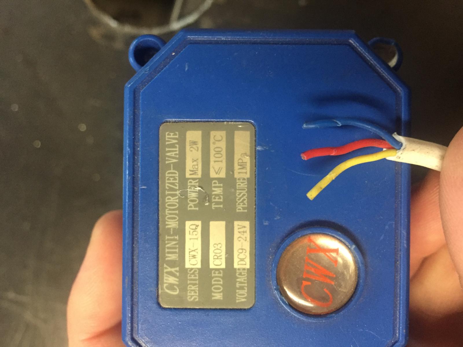
this is a 3 wire single way ball valve

image.jpg
 
day trippr: Thanks a bunch! that is totally what I need!
Playing with the valves on a dc power supply I have I can get them to open and close. the 3 way can't be used for metering so thinking a simple switch for that one, but the normal ball valve will meter if power is only attached breifly so thinking a momentary switch there. Any better ideas? Also, haven't exactly figured out which of the 3 wires need to be connected where (just switched stuff up until it worked) but I don't really understand why their are 3 wires. I habe some 2 wire valves that work the same as the 3 wire. Anyone know why there are 3 wires? (to get it to open and close I just connected two of the 3 to positive and another to negative.
Thanks,
Pat
 
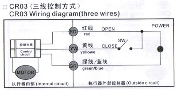
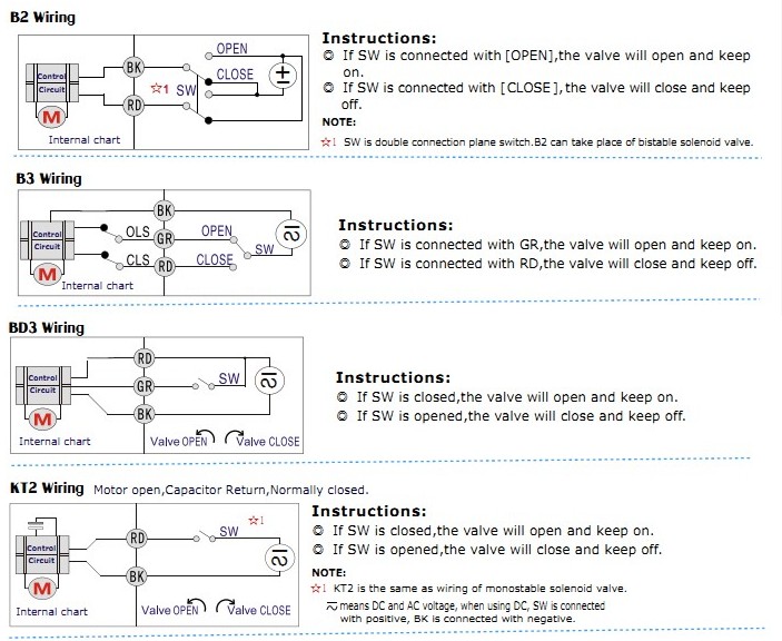
Given the functionality shown in the diagrams, two of the three wires are the voltage source and ground return and power "always on" components that examine the state of the third wire and act accordingly. In that configuration it's possible to use a low current signal for that third wire, with all the motor load being induced on the first pair of wires.

While you might be able to get "something to happen" using pairs of wires, you should follow the appropriate diagram so you don't toast anything...

Cheers!
 
The valves that only have 2 wires rely on a spring to close. The 3 wire valves use the motor to close the valve. In this case you need the third wire to supply power to the motor.
 
I can tell you how to hook these up if you can tell me what you are controlling (what you want the valve installed in) and what you are using for a controller (Ranco..PID..switch...whatever). One of your wires is a "common" and one of the others is power to open and the other is power to close. They are usually used with a set of normally open and normally closed contact so that for example above your set point the normally open contacts close and it provides power to the open side and opens the valve...when conditions are met the normally open contacts open again taking power off the open side of the valve and the normally closed contacts close again providing power to the close side of your valve...closing the valve. A bit more info and we can get you sorted. You will still need a 12v power supply of some sort but they are cheap.
 
http://www.auberins.com/index.php?main_page=product_info&cPath=7_32&products_id=236

One of these is what you want if you are controlling manually. Your +12v power supply goes to each contact on the switch (connect the power to the switch and use a small jumper wire between the NO and NC contacts) and your open wire of the ball valve goes to one side and your close wire to the other..the 3rd "common" wire on the ball valve goes to the -12v of the power supply. When you turn the switch one way it opens..the other way it closes...if you want it the other way around just switch the wires from the valve around.
 
Thanks thevalkrye,
I am set though. Using the woring diagrams that the other person posted I was actually able to build a system using a rocker switch and a momentary switch and get the valve to be a metering valve which is awesome as NO or NC would have been a pain to use.
I appreciate your reply and offer to help though!
 
Back
Top