Heating element on, even when PID not sending signal

Homebrew Talk - Beer, Wine, Mead, & Cider Brewing Discussion Forum

Help Support Homebrew Talk - Beer, Wine, Mead, & Cider Brewing Discussion Forum:

This site may earn a commission from merchant affiliate links, including eBay, Amazon, and others.

Adrian Gresores

Well-Known Member
Joined
Nov 16, 2019
Messages
49
Reaction score
9
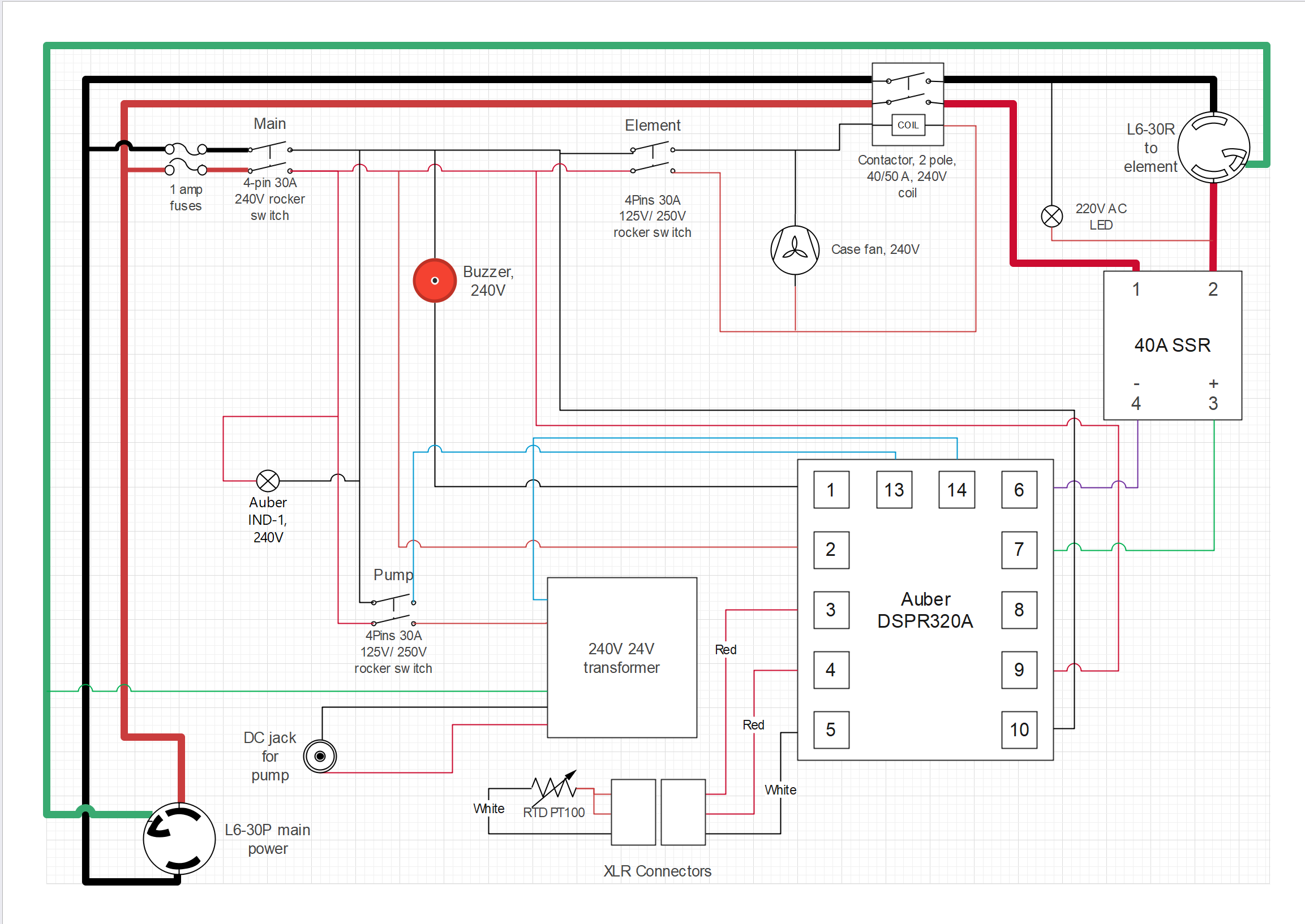
Lately, I have been having a big problem with my controller panel. Specifically, power is being sent to the heating element even before any program is running on the DSRP320A (top line shows current water temperature and lower line shows STOP). For reference, if I only turn on the main power switch, there is a minimal voltage from the controller to the SSR (8 mV), and no voltage from the output terminals on the SSR (1 and 2). Resistance between 3 and 4 shows an open circuit. However, as soon as I flip the element switch on, the element LED turns on and the voltage between SSR terminals 1 and 2 goes to 115V. The LED on the SSR never turns on, though. Again, this is before I begin running any program. I have already replaced the SSR once, with no change. Any idea where the problem lies?

Mash_Boil controller diagram with buzzer.png
 
Is the element connected when this happens? SSRs have some unexpected (by non-electronics experts) behavior when there is no significant load attached.

And, 115V should not show up anywhere in your panel, unless you are measuring from a hot to ground. The voltage between terminals 3 & 4 of the SSR should never be more than about 12V DC. Any higher reading is a serious problem.

Brew on :mug:
It happens both when the element is connected and when it is not.

I miswrote when I first entered this message. I corrected it to terminals 1 and 2 of the SSR.
 
It happens both when the element is connected and when it is not.

I miswrote when I first entered this message. I corrected it to terminals 1 and 2 of the SSR.
Just noticed your fan. You need to move the connections for that, as the fan provides a leakage path that will affect the Element Firing Lamp. I'd recommend wiring the fan in parallel with the Element Contactor Coil.

Brew on :mug:
 
Last edited:
Just noticed your fan. You need to move the connections for that, as the fan provides a leakage path that will affect the Element Firing Lamp. I'd recommend wiring the fan in parallel with the Element Contactor Coil.

Brew on :mug:
So this? Will that fix the 115V output between SSR 1 and 2?

Mash_Boil controller diagram with buzzer v.2.png
 
I think it might. I want to draw up an equivalent circuit model to analyze voltage drops.

Brew on :mug:
 
I think it might. I want to draw up an equivalent circuit model to analyze voltage drops.

Brew on :mug:
I know the voltage should be 0 or 240 across SSR 1 and 2. I don't understand the 115V and, even more, why there is any voltage when the controller isn't sending a significant voltage to 3 and 4.
 
I know the voltage should be 0 or 240 across SSR 1 and 2. I don't understand the 115V and, even more, why there is any voltage when the controller isn't sending a significant voltage to 3 and 4.
An SSR is not a perfect switch. Below is an approximate equivalent circuit for an SSR, which explains some of the quirks that they have.

SSR Model.PNG


I want to add the lamp and fan to this circuit model, and look at the implications.

Do you have the Mfg and model information for your fan?

Brew on :mug:
 
An SSR is not a perfect switch. Below is an approximate equivalent circuit for an SSR, which explains some of the quirks that they have.

View attachment 847653

I want to add the lamp and fan to this circuit model, and look at the implications.

Do you have the Mfg and model information for your fan?

Brew on :mug:
And this is the element firing lamp.
 
It happens both when the element is connected and when it is not.
Is the element getting hot when it is connected.
why there is any voltage when the controller isn't sending a significant voltage to 3 and 4.
You should expect to see a voltage difference over the SSR 1 & 2 terminals when itnis "off" as the SSR is essentially an open switch, when it is on you should expect to see 0v. So regarding measuing voltages, what you are seeing is what you should expect (apart from the 120v instead of 240v).
The led lighting is normally due to the fact SSR leak a minute bit of current when off, usually around 10ma. This isn't enough to be noticeable in the heating element but can be enough to light an led. The weird thing is normally plugging the element in stops this as basically the element is an easier path for the leakage current to take.

I would be checking your wiring and make sure you haven't inadvertently wired something to ground instead of L1 or L2 - start with the plugs and the fan and LED.
 
Last edited by a moderator:
Is the element getting hot when it is connected.

You should expect to see a voltage difference over the SSR 1 & 2 terminals when itnis "off" as the SSR is essentially an open switch, when it is on you should expect to see 0v. So regarding measuing voltages, what you are seeing is what you should expect (apart from the 120v instead of 240v).
The led lighting is normally due to the fact SSR leak a minute bit of current when off, usually around 10ma. This isn't enough to be noticeable in the heating element but can be enough to light an led. The weird thing is normally plugging the element in stops this as basically the element is an easier path for the leakage current to take.

I would be checking your wiring and make sure you haven't inadvertently wired something to ground instead of L1 or L2 - start with the plugs and the fan and LED.
Yes, the element is getting hot. I do plan to check all the wiring.

I hadn't mentioned that I have been using this panel, as is, for a couple of years now. It had been working perfectly. I only made 2 changes recently. I switched a DSPR120 to a DSPR320A, and added the buzzer (for now, the buzzer is actually disconnected). The controller is connected correctly, but I am still going to check it, and everything else, later today.
 
I assume the SSR input range is the same as the old one and accommodates 12 Vdc.
Use caution working around live wires below!
What happens if you disconnect terminal 6 and 7 from the dsp320 (with power off then repower to measure) , turn on the element switch and check the output of the ssr ? If you have an amp meter, check line of terminal 2 of ssr for low or no amps (assume something is plugged in like heating element, or light or motor). Voltage may be 115 or 240 depending on where you check terminal 2 against due to normal small leakage in ssr's.
While you still have the wires off, check if terminal 6 and 7 shows 12 Vdc with the controller showing STOP ( it should not).
These readings should point to an ssr problem or a dsp320 problem.
 
I would suspect either the SSR has failed
This makes the most sense, except for the voltage measurements and that this is the second SSR to behave like this.
@Adrian Gresores
From what you describe it sounds like you have a short to ground between your element and SSR terminal 2.
Can you take some photos of the actual wiring for us?
Also are you running this through a GFCI?
Also use your multimeter to check continuity between the SSR terminal 2 and ground.
 
Last edited:
I appreciate all your advice. I will go through them and try them. Unfortunately, I didn't get a chance, before we left on vacation today.
 
Relative to @mattd2 's comments: Do you have (you should for your protection) a GFCI breaker protecting the power feed to your control panel? If so, you should test it with "Test" button on the breaker to make sure it is working correctly. If it is working correctly, then any short or leakage to ground would trip the GFCI. So, a short or leak to ground would be highly unlikely if you have a working GFCI.

Brew on :mug:
It is a GFCI breaker and I will test it.
 
Relative to @mattd2 's comments: Do you have (you should for your protection) a GFCI breaker protecting the power feed to your control panel? If so, you should test it with "Test" button on the breaker to make sure it is working correctly. If it is working correctly, then any short or leakage to ground would trip the GFCI. So, a short or leak to ground would be highly unlikely if you have a working GFCI.

Brew on :mug:
One more piece of advice requested...Now, that I have gotten everything to work, and since I can't stop myself from tinkering, I would like to connect the controller's relay 2 to my pump. It would then turn on automatically during mash steps, as per its programming. Would the wiring for that be as simple as the blue lines below? I realize that would make the pump switch essentially superfluous, but, oh well, it's already there.

Mash_Boil controller diagram with buzzer and pump relay.png
 

Attachments

  • Mash_Boil controller diagram with buzzer and pump relay.png
    Mash_Boil controller diagram with buzzer and pump relay.png
    222.1 KB · Views: 1
One more piece of advice requested...Now, that I have gotten everything to work, and since I can't stop myself from tinkering, I would like to connect the controller's relay 2 to my pump. It would then turn on automatically during mash steps, as per its programming. Would the wiring for that be as simple as the blue lines below? I realize that would make the pump switch essentially superfluous, but, oh well, it's already there.

View attachment 848321
Yes.

I wouldn't say the pump switch is superfluous. You can use it to shut off the pump during the mash, without having to mess with the DSPR's programming. It's always good to have manual ways to shut different parts of the panel down, both for flexibility in operations, and to deal with unexpected circumstances.

Brew on :mug:
Thank you again.
 
Back
Top