Efficient Octagonal CPVC manifold for Rubbermaids:
I've gotten many PM's about my manifold so I thought I do a write-up.
I began using Flyguy's easy braided hose rubbermaid conversion. I eventually tore up a couple of hoses and experienced too varied efficiencies. I decided I needed a quality manifold capable of fly sparging. This design would work great for batch sparging as well. I was inspired by another HBT member for this design, but have made some improvements I think.
Follow FlyGuy's popular tutorial here but eliminate the hose clamps, hose, brass square head plug, and 3/8" male barb adapter.
Internal parts:
-5 feet of 1/2" CPVC pipe (at least)
-8 1/2" CPVC 45 degree elbows
-3 1/2" CPVC tees
-1 1/2" CPVC FIP adapter (though mine was not labelled FIP, I think it's basically the same, I can't recall what it was labelled)
-1 90 degree CPVC street elbow
-Optional parts could include some brass fittings depending on the availability of CPVC fittings at your local HD. Mine uses two different brass fittings from the brass nipple to extend the manifold connection into the cooler farther. This was also due to the availability of parts at the time I made this. Basically, if your HD has the proper CPVC adapter (one that fits directly on the brass nipple), there shouldn't really be a need for additional brass fittings.
All prepared pieces:

Cuts:
You'll want to use a Dremel for this, though I suppose the slots could be drilled instead.
From the 5' pipe cut:
-6 3" pieces. These will need to be slotted as shown in the picture.
-4 1" pieces without slots.
-2 3.5" pieces without slots.
-1 4.5" piece without slots. This will be bent as shown in the picture. I used a torch to do this. Holding the piece a few feet away from the torch and slowly spinning it allowed the piece to bend without burning it, like toasting a marshmallow. Also, this may need to be shorter or longer depending on how far the adapter extends from the cooler wall. Basically, cut to the size that will center the octagon in your cooler.
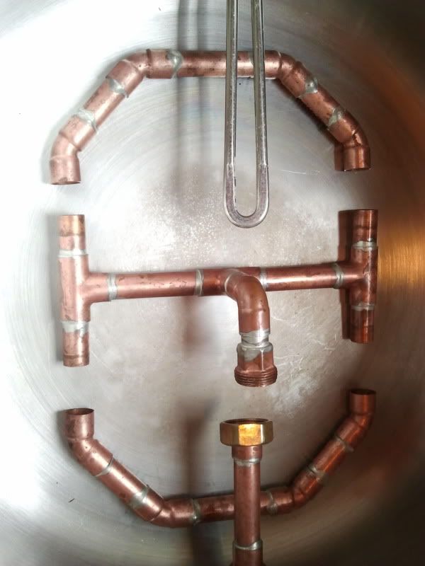
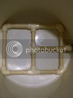
Cross section with 1" pieces connected to tees:

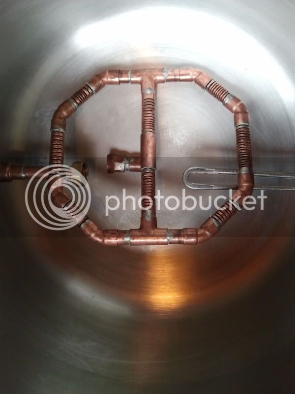
Top of assembled octagon:

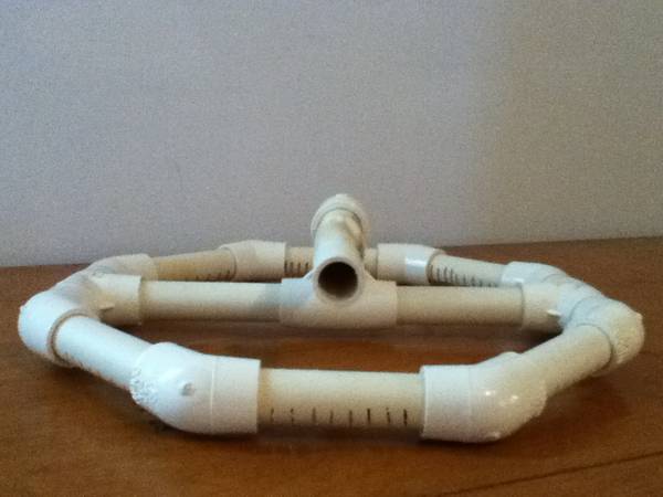
Bottom of assembled octagon:

Bent 4.5" piece connected:

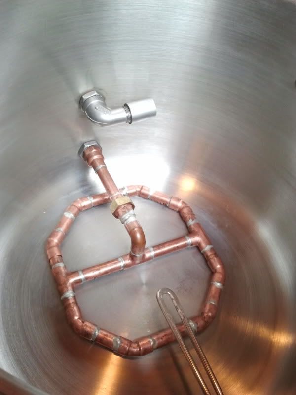
Adapter and brass fittings in place and connected to nipple:

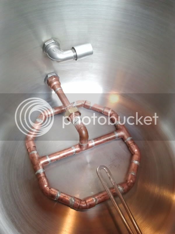
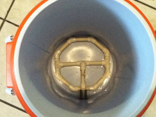
Manifold in place and sitting flush:

The bend in the 4.5" piece is crucial for the manifold to sit flush and reduce dead space.
Overall, I wouldn't change anything about my design. I'm quite happy with it. The best part about this design compared to other manifolds IMO is that it pulls the wort from the middle of the octagon. Most designs connect to the spigot directly from the edge of the manifold next to the cooler wall, creating more channeling than this design– which is especially necessary for fly sparging.
My system is designed to 77% efficiency for normal size mashes. Since I fly sparge this is directly related to the flow rate, which is 1qt per minute. If I go slightly faster I might get 75%, slightly slower and I might get 80%. I guarantee I can get much higher efficiencies than 80%, but that is not what I am looking to do.
I've gotten many PM's about my manifold so I thought I do a write-up.
I began using Flyguy's easy braided hose rubbermaid conversion. I eventually tore up a couple of hoses and experienced too varied efficiencies. I decided I needed a quality manifold capable of fly sparging. This design would work great for batch sparging as well. I was inspired by another HBT member for this design, but have made some improvements I think.
Follow FlyGuy's popular tutorial here but eliminate the hose clamps, hose, brass square head plug, and 3/8" male barb adapter.
Internal parts:
-5 feet of 1/2" CPVC pipe (at least)
-8 1/2" CPVC 45 degree elbows
-3 1/2" CPVC tees
-1 1/2" CPVC FIP adapter (though mine was not labelled FIP, I think it's basically the same, I can't recall what it was labelled)
-1 90 degree CPVC street elbow
-Optional parts could include some brass fittings depending on the availability of CPVC fittings at your local HD. Mine uses two different brass fittings from the brass nipple to extend the manifold connection into the cooler farther. This was also due to the availability of parts at the time I made this. Basically, if your HD has the proper CPVC adapter (one that fits directly on the brass nipple), there shouldn't really be a need for additional brass fittings.
All prepared pieces:
Cuts:
You'll want to use a Dremel for this, though I suppose the slots could be drilled instead.
From the 5' pipe cut:
-6 3" pieces. These will need to be slotted as shown in the picture.
-4 1" pieces without slots.
-2 3.5" pieces without slots.
-1 4.5" piece without slots. This will be bent as shown in the picture. I used a torch to do this. Holding the piece a few feet away from the torch and slowly spinning it allowed the piece to bend without burning it, like toasting a marshmallow. Also, this may need to be shorter or longer depending on how far the adapter extends from the cooler wall. Basically, cut to the size that will center the octagon in your cooler.
Cross section with 1" pieces connected to tees:
Top of assembled octagon:
Bottom of assembled octagon:
Bent 4.5" piece connected:
Adapter and brass fittings in place and connected to nipple:
Manifold in place and sitting flush:
The bend in the 4.5" piece is crucial for the manifold to sit flush and reduce dead space.
Overall, I wouldn't change anything about my design. I'm quite happy with it. The best part about this design compared to other manifolds IMO is that it pulls the wort from the middle of the octagon. Most designs connect to the spigot directly from the edge of the manifold next to the cooler wall, creating more channeling than this design– which is especially necessary for fly sparging.
My system is designed to 77% efficiency for normal size mashes. Since I fly sparge this is directly related to the flow rate, which is 1qt per minute. If I go slightly faster I might get 75%, slightly slower and I might get 80%. I guarantee I can get much higher efficiencies than 80%, but that is not what I am looking to do.


")