You are using an out of date browser. It may not display this or other websites correctly.
You should upgrade or use an alternative browser.
You should upgrade or use an alternative browser.
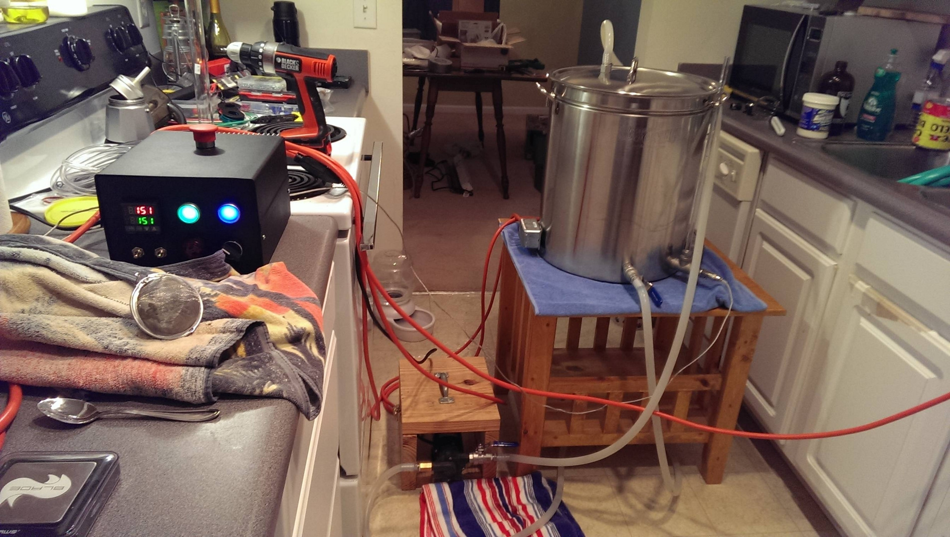
Dual 2000W 120V Recirculating eBIAB Build
- Thread starter russki
- Start date

Help Support Homebrew Talk - Beer, Wine, Mead, & Cider Brewing Discussion Forum:
This site may earn a commission from merchant affiliate
links, including eBay, Amazon, and others.
OP
OP
russki
Well-Known Member
Sorry if this has been covered...but what is it like brewing with this indoors? Do you have problems with condensation? Do you need a lot of air flow?
I brew in the kitchen without any extra ventilation; never had any problems with condensation. But then I do have 9ft ceilings, and air in my house is pretty dry (under 30% humidity), so it just acts as a giant humidifier. It's not much different than stovetop brewing in terms of humidity.
Weezy
Well-Known Member
Condensation? As long as you're not brewing in a especially tiny room, it's fine. The people who really run into problems are running much bigger rigs and bigger batches, with a lot more boil off and evaporation.
sorry to revive an old thread...but I am having problems understanding exactly why the contactors are necessary. Why couldn't I just place the power switches/buttons between the PID and each SSR and leave out contactors? or even between the SSR and element? Are they really needed? i have been reading around quite a bit and just don't seem to understand. Thanks for the help
Which diagram are you referencing? A link would help a lot.sorry to revive an old thread...but I am having problems understanding exactly why the contactors are necessary. Why couldn't I just place the power switches/buttons between the PID and each SSR and leave out contactors? or even between the SSR and element? Are they really needed? i have been reading around quite a bit and just don't seem to understand. Thanks for the help
P-J
sorry to revive an old thread...but I am having problems understanding exactly why the contactors are necessary. Why couldn't I just place the power switches/buttons between the PID and each SSR and leave out contactors? or even between the SSR and element? Are they really needed? i have been reading around quite a bit and just don't seem to understand. Thanks for the help
Which diagram are you referencing? A link would help a lot.
P-J
Ok, got it. The contactors are in place due to the fact that the switches involved cannot handle the current draw to drectly energize the heating elements. The elements draw 17A and the switches wanted for the original design cannot handle that current draw.hey thanks for the quick reply! I am planning on using the 2-element 120V diagram from the first post in this thread

It is all about design choices for the person wanting to do an E-Brew set up. Generally they spell it out and I take the time to draw a diagram to help them.
P-J
HopRodGR
Well-Known Member
P-J,
I'm still looking to start my dual 2000w control panel, hopefully soon.
I'll be honest, I'm not hooked on any particular design, I just want functionality. That being said, if the contactors are there only because of the choice of the pushbutton switches, do you have a drawing that uses switches that can handle the load going to the elements, which if I'm understanding correctly, eliminates the need for the contactors? Seems as though that would free up space in the control box and simplify the wiring.
P-J said:Ok, got it. The contactors are in place due to the fact that the switches involved cannot handle the current draw to drectly energize the heating elements. The elements draw 17A and the switches wanted for the original design cannot handle that current draw. It is all about design choices for the person wanting to do an E-Brew set up. Generally they spell it out and I take the time to draw a diagram to help them. P-J
iijakii
Well-Known Member
Yeah, you can simply use a 20A switch in place of it. Have one leg going from switch-outletand then the SSR inbetween the other leg and the outlet.
If you're not wanting a blingy panel have you considered a switch/outlet combo? I'll be using this for my element receptacle on my next panel http://www.amazon.com/dp/B003AU6R2M/?tag=skimlinks_replacement-20
If you're not wanting a blingy panel have you considered a switch/outlet combo? I'll be using this for my element receptacle on my next panel http://www.amazon.com/dp/B003AU6R2M/?tag=skimlinks_replacement-20
Last edited by a moderator:
HopRodGR
Well-Known Member
Of course I missed something that simple. 
On second thought though, P-J's drawing below eliminates a switch and a contactor, which in that small Auberins box, would free up quite a bit of space. I think I like this layout since controlling the two elements independently isn't really important to me.

On second thought though, P-J's drawing below eliminates a switch and a contactor, which in that small Auberins box, would free up quite a bit of space. I think I like this layout since controlling the two elements independently isn't really important to me.
Yeah, you can simply use a 20A switch in place of it. Have one leg going from switch-outletand then the SSR inbetween the other leg and the outlet.
If you're not wanting a blingy panel have you considered a switch/outlet combo? I'll be using this for my element receptacle on my next panel http://www.amazon.com/dp/B003AU6R2M/?tag=skimlinks_replacement-20
Last edited by a moderator:
iijakii
Well-Known Member
That's a pretty interesting route, but personally I'd prefer to just use one element with the PID and one simply either on/off. You don't need both for the mash and only need one for heating times and/or boil, ya? Could save on one SSR and a lot of complexity, I think.
HopRodGR
Well-Known Member
If I'm doing 5 gallon batches, one 2000 watt element won't be enough for reasonable ramp times or a good rolling boil. Plus, I'd like the option to do 10 gallon batches from time to time.
iijakii said:That's a pretty interesting route, but personally I'd prefer to just use one element with the PID and one simply either on/off. You don't need both for the mash and only need one for heating times and/or boil, ya? Could save on one SSR and a lot of complexity, I think.
pvtschultz
Well-Known Member
How is the pump doing now? Any more problems with it? I received a modest Christmas bonus this year and want to add a pump to my setup.
OP
OP
russki
Well-Known Member
How is the pump doing now? Any more problems with it? I received a modest Christmas bonus this year and want to add a pump to my setup.
I'm pretty much done with this pump - it left me stranded in the middle of a brew day twice, both times when recirculating boiling wort to sanitize my plate chiller, leaving me to gravity feed through the chiller. Took the pump apart, and the impeller shaft had seized - I got it cleaned up, put some keg lube on it, and it's working again, but I've had it with unreliable equipment.
I just got a Chugger pump from BobbyM, haven't used it yet, but it seems to be a much better option for not much more. I do not recommend the GreatBrewEh/US Solar pump.
Great thread, thanks for posting your build! I'm starting a similar build and have a quick question, for Russki or anyone else willing to help.
When mounting the SSR's to the enclosure, do you:
1) Cut the enclosure in order to mount SSR's to the heatsink, then bolt heatsink to enclosure
or
2) Bolt SSR's to enclosure back plate and then bolt heatsink to other side back (i.e no ssr cutout)?
Thanks in advance!!
When mounting the SSR's to the enclosure, do you:
1) Cut the enclosure in order to mount SSR's to the heatsink, then bolt heatsink to enclosure
or
2) Bolt SSR's to enclosure back plate and then bolt heatsink to other side back (i.e no ssr cutout)?
Thanks in advance!!
I'm pretty much done with this pump - it left me stranded in the middle of a brew day twice, both times when recirculating boiling wort to sanitize my plate chiller, leaving me to gravity feed through the chiller. Took the pump apart, and the impeller shaft had seized - I got it cleaned up, put some keg lube on it, and it's working again, but I've had it with unreliable equipment.
I just got a Chugger pump from BobbyM, haven't used it yet, but it seems to be a much better option for not much more. I do not recommend the GreatBrewEh/US Solar pump.
Hey Russki! Long time no talk. When you say you got the chugger pump did you get the stainless and polysulfone head? Inline or center?
Option #1: The SSR should be mounted directly to the heat sink using thermal grease. Therefore you need to do a cutout for it in the control panel.Great thread, thanks for posting your build! I'm starting a similar build and have a quick question, for Russki or anyone else willing to help.
When mounting the SSR's to the enclosure, do you:
1) Cut the enclosure in order to mount SSR's to the heatsink, then bolt heatsink to enclosure
or
2) Bolt SSR's to enclosure back plate and then bolt heatsink to other side back (i.e no ssr cutout)?
Thanks in advance!!
Hope this help you.
P-J
Many thanks P-J! Not only for your answer, but your diagrams and other guidance in these threads.
Thanks again to Russki for putting your build up here!
I can't wait to get this all set up and crank out a batch! I may have one or two other questions along the way, hope it's ok to put them in here!
Onward!
Thanks again to Russki for putting your build up here!
I can't wait to get this all set up and crank out a batch! I may have one or two other questions along the way, hope it's ok to put them in here!
Onward!
HopRodGR
Well-Known Member
I don't believe this has been posted yet, but for those doing the same type of modification to the back of the Auberins box like russki did (I am), this heatsink, which is 135x105x33.5mm, looks to fit very nicely on the back without modification, and gives enough room to install the handy box extension.
Sorry to keep bringing this thread back, but I had a question about the plug that was used in this build. I have been looking around for 20 A 120 V plugs and they seem to use the 'T' style plugs rather than a 'normal' 120 V plug...is this necessary? I will be using 2000 W elements, which should pull just under 17 A if I understand correctly. Will I be okay using a 120 V 15 A 'normal' plug or do I need to use these?
iijakii
Well-Known Member
Sorry to keep bringing this thread back, but I had a question about the plug that was used in this build. I have been looking around for 20 A 120 V plugs and they seem to use the 'T' style plugs rather than a 'normal' 120 V plug...is this necessary? I will be using 2000 W elements, which should pull just under 17 A if I understand correctly. Will I be okay using a 120 V 15 A 'normal' plug or do I need to use these?
https://www.homebrewtalk.com/f51/countertop-brutus-20-a-131411/index21.html#post5744471
southwoodbrew
Active Member
- Joined
- Aug 24, 2012
- Messages
- 29
- Reaction score
- 4
I gave up on trying to see if anyone else mentioned this, but I noticed you mentioned priming issues with that pump, I have the same one, and the documentation said to not use it in the orientation you have it, the pump body should be off to the side, not below the head.
OP
OP
russki
Well-Known Member
2 SSRs - one per element.Trying to follow how many ssr's you used. Per the diagram there were 4.
OP
OP
russki
Well-Known Member
That's good to know, although I figured out the priming issue even with the "impeller on top" configuration. My problem with that pump was that it quit in the middle of two brews; once from overheating, and second time when the shaft seized. I've been using a Chugger for the last 3 brews, and couldn't be happier with it.I gave up on trying to see if anyone else mentioned this, but I noticed you mentioned priming issues with that pump, I have the same one, and the documentation said to not use it in the orientation you have it, the pump body should be off to the side, not below the head.
jybingbrew
Well-Known Member
Great build! Curious - is there a hole on the back of the case to attach the SSR directly to the heat sink, or does the heat just dissipate through the case to the heat sink?
Sent from my iPad using Home Brew
Sent from my iPad using Home Brew
PistolsAtDawn
Well-Known Member
Well done, russki! I have been looking to build something like this for a long time. This is perfect for my purposes. I am basically going to clone this build. I really want to thank everyone for contributing to this thread (and to all the others like it). This has given me the confidence to get started on my own setup (and my tax return has given me the funds fortunately).
P-J, I too need your assistance, please. There is at least one change I'd like to make to that wiring diagram: I don't really need for the extra LED push button switches for the elements. The other two seem easier since they don't need contactors, so I'll leave those in place. Removing those push button switches and the contactors seems to simplify the wiring and free up room in what looks to be a crowded enclosure. I like the extra room since my wiring work isn't the best.
If I were to do that, could I use some 20a 120v toggle switches of some sort? Maybe like this one?
http://www.amazon.com/Heavy-Duty-Toggle-Switch-SPST/dp/B0002ZPBRA/
HopRodGR mentioned this in post #90, and iijakii mentioned a basic outlet/switch combo in post #91. I like that too, but it seems like the single outlet handy box just barely fit on the enclosure, and I don't really want a larger one hanging off the side if possible. I guess I could always mount the SSRs and heatsinks to the top instead of the back to make everything fit.
With the two combo outlets in mind, I tried modifying your diagram. Does that seem close? How might toggle switches fit in to that diagram?
Really my goal is function over form, and I'm trying to clone this build while trimming certain bits for economy (camlocks, sight glass, etc.).
Any advice you might have for me would be most appreciated!
Ok, got it. The contactors are in place due to the fact that the switches involved cannot handle the current draw to drectly energize the heating elements. The elements draw 17A and the switches wanted for the original design cannot handle that current draw.
It is all about design choices for the person wanting to do an E-Brew set up. Generally they spell it out and I take the time to draw a diagram to help them.
P-J
P-J, I too need your assistance, please. There is at least one change I'd like to make to that wiring diagram: I don't really need for the extra LED push button switches for the elements. The other two seem easier since they don't need contactors, so I'll leave those in place. Removing those push button switches and the contactors seems to simplify the wiring and free up room in what looks to be a crowded enclosure. I like the extra room since my wiring work isn't the best.
If I were to do that, could I use some 20a 120v toggle switches of some sort? Maybe like this one?
http://www.amazon.com/Heavy-Duty-Toggle-Switch-SPST/dp/B0002ZPBRA/
HopRodGR mentioned this in post #90, and iijakii mentioned a basic outlet/switch combo in post #91. I like that too, but it seems like the single outlet handy box just barely fit on the enclosure, and I don't really want a larger one hanging off the side if possible. I guess I could always mount the SSRs and heatsinks to the top instead of the back to make everything fit.
With the two combo outlets in mind, I tried modifying your diagram. Does that seem close? How might toggle switches fit in to that diagram?
Really my goal is function over form, and I'm trying to clone this build while trimming certain bits for economy (camlocks, sight glass, etc.).
Any advice you might have for me would be most appreciated!
Last edited by a moderator:
Well done! I have been looking to build something like this for a long time. This is basically perfect for my purposes. I am basically going to clone this build. I really want to thank everyone for contributing to this thread (and to all the others like it). This has given me the confidence to get started on my own setup (and my tax return has given me the funds fortunately).
P-J, I need your assistance, please. There is at least one change I'd like to make to that wiring diagram: I don't feel the need for the extra LED push button switches for the elements. For my purposes, that's extra bling that I don't care about very much (the other two seem easier since they don't need contactors, so I'll leave those in place).
Removing those and the contactors seems to simplify the wiring and free up room in what looks to be a crowded enclosure. If I were to do that, could I use some 20a 120v toggle switches of some sort? Maybe like this one (click)?
HopRodGR mentioned this in post #90 and iijakii mentioned a basic outlet/switch combo in post #91. I like that too, but wouldn't that then require a bigger handy box to account for both combo outlets? It seems like the single outlet handy box just barely fit on the enclosure, and I don't really want a larger one hanging off if possible. I guess I could always mount the SSRs and heatsinks to the top instead of the back to make everything fit.
All well said, however, What diagram are you referring to? A link would help me help you. No? -
whatever...
Last edited by a moderator:
iijakii
Well-Known Member
Well done! I have been looking to build something like this for a long time. This is perfect for my purposes. I am basically going to clone this build. I really want to thank everyone for contributing to this thread (and to all the others like it). This has given me the confidence to get started on my own setup (and my tax return has given me the funds fortunately).
P-J, I too need your assistance, please. There is at least one change I'd like to make to that wiring diagram: I don't really need for the extra LED push button switches for the elements. The other two seem easier since they don't need contactors, so I'll leave those in place. Removing those push button switches and the contactors seems to simplify the wiring and free up room in what looks to be a crowded enclosure. I like the extra room since my wiring work isn't the best.
If I were to do that, could I use some 20a 120v toggle switches of some sort? Maybe like this one?
http://www.amazon.com/Heavy-Duty-Toggle-Switch-SPST/dp/B0002ZPBRA/
HopRodGR mentioned this in post #90, and iijakii mentioned a basic outlet/switch combo in post #91. I like that too, but it seems like the single outlet handy box just barely fit on the enclosure, and I don't really want a larger one hanging off the side if possible. I guess I could always mount the SSRs and heatsinks to the top instead of the back to make everything fit.
With the two combo outlets in mind, I tried modifying your diagram. Does that seem close? How might toggle switches fit in to that diagram?
Really my goal is function over form, and I'm trying to clone this build while trimming certain bits for economy (camlocks, sight glass, etc.).
Any advice you might have for me would be most appreciated!
It's really simple on 120v.. If you want to use a rated toggle-switch instead of a fancy switch+contactor combo, you just place it inbetween the SSR and outlet on your hot.
Last edited by a moderator:
PistolsAtDawn
Well-Known Member
All well said, however, What diagram are you referring to? A link would help me help you. No? -
whatever...
You must have caught me during an edit that I hadn't saved yet. I've been trying to nail down sources for parts for way too long now. Yikes, it's 4am. I didn't think you'd see this so soon. Sorry about that. Please see my prior post.
PistolsAtDawn
Well-Known Member
It's really simple on 120v.. If you want to use a rated toggle-switch instead of a fancy switch+contactor combo, you just place it inbetween the SSR and outlet on your hot.
Thank you. I figured as much, but I don't trust my own limited knowledge enough to work with this much electricity without double checking. The biggest project I've tackled up till now would be my MAME cabinet.
PistolsAtDawn
Well-Known Member
So I've been busting my hind quarters working on this, and I managed to finish in just under 3 weeks (plus a week for shipping times). I'm beyond happy with how this turned out. I'm thinking of calling her "Dolly." Hopefully she lives longer than that sheep.
I need to give a big thanks to russki, especially to P-J for all those great diagrams, and everyone else who shares their designs on these awesome projects. I couldn't have built this without you guys!
I ran a inaugural batch through it last night (a 5-gallon batch of Cream of Three Crops). Hit my OG dead on. That was definitely the easiest all-grain batch of beer I've ever made.
russki, other than running auto-tune, setting the input type to the proper RTD setting, setting the alarm function to the right terminal number and enabling manual mode switching, was there anything specific you modified in the PID parameters?
CountryGravy
Well-Known Member
Great looking rig!
Subscribed for future reference, in case I don't pursue induction.
Subscribed for future reference, in case I don't pursue induction.
PistolsAtDawn
Well-Known Member
Great looking rig!
Subscribed for future reference, in case I don't pursue induction.
I'm curious about your induction plans. Care to extrapolate?
OP
OP
russki
Well-Known Member
Nice build! Nope, that's all I did, and it's been working great. One thing I do differently now is I set the strike temperature to my target mash temp (i.e. if I'm mashing at 152F, that's what I set the on the PID from the get go); otherwise it seemed to overshoot my mash temp.russki, other than running auto-tune, setting the input type to the proper RTD setting, setting the alarm function to the right terminal number and enabling manual mode switching, was there anything specific you modified in the PID parameters?
Have fun with your new toy!
PistolsAtDawn
Well-Known Member
Nice build! Nope, that's all I did, and it's been working great. One thing I do differently now is I set the strike temperature to my target mash temp (i.e. if I'm mashing at 152F, that's what I set the on the PID from the get go); otherwise it seemed to overshoot my mash temp.
Have fun with your new toy!
I already am having fun!

I overshot my first mash by 6 degrees, but pretty quickly corrected it with some cold water. I'll make note that there's no need to adjust for the grain temperature. The response time is impressive on this thing!
One quick note: the part number (but not description) you had listed for the RTD probe was for the 1/4" NTP thread, not the 1/2". Nothing a $1.15 coupling couldn't fix though.
Thanks again, bud!
Similar threads
- Replies
- 14
- Views
- 1K
- Replies
- 4
- Views
- 1K
- Replies
- 0
- Views
- 455
