Was hoping I might get a review of my schematic. Looks simple and straightforward to me, but it has been at least fifteen years since I have done any sort of electronics projects. I have a non-programmable digital thermostat already laying around that needs a use, so with warmer temperatures hopefully soon to come, a temperature controller for my upcoming fermentation chamber seemed to be in order. 
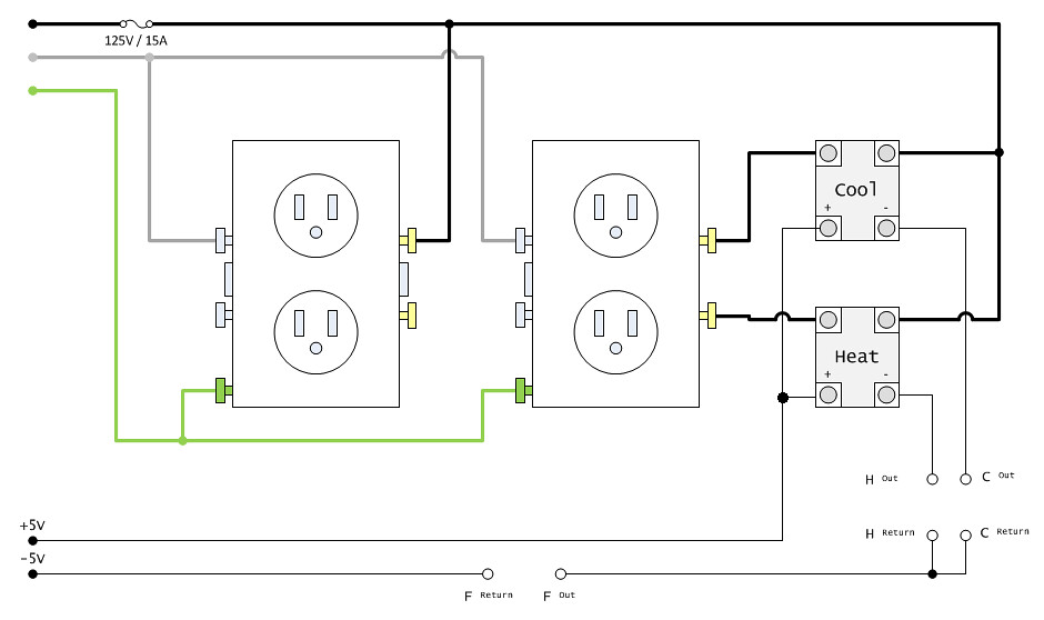
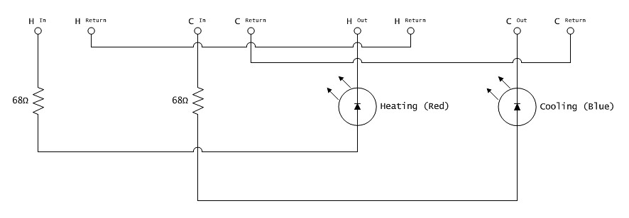
Basically, this will hook up to a non-programmable digital thermostat. Two outlets, the one on the left always live and the one on the right is split. All the Out / Return pairs are wired to phono jacks, for quick connection points. H-Out goes to the heating relay lead on the thermostat, C-Out goes to the cooling relay lead on the thermostat. Since only one of the relays is active at one time, the only leg that should be live would be the relay position that is closed.
Because of the fact that only one of the heating or cooling relays would be active at once, if at all, the SSRs should be only be powered when that leg is closed. So, both H-Return and C-Return are wired to the common ground of the thermostat. F-Out and F-Return are to the fan that will be attached, as well. The fan should only be powered when either the heating or cooling leg is closed.
Not pictured, there is a small enclosure that the H pair and C pair run through that will provide a red and blue LED en route to the thermostat. This enclosure would be optional, and haven't decided if I care to have it yet. Figured since the main enclosure will mount on the back of my fermentation chamber, I would need a way to put indicators on the front, if I end up wanting them.
Any feedback / critiques would be appreciated. Was hoping to begin the build tomorrow, as I have everything already laying around the house, apart from a couple of 15 amp outlets.
Cheers!