Could someone review my wiring diagram?

Homebrew Talk - Beer, Wine, Mead, & Cider Brewing Discussion Forum

Help Support Homebrew Talk - Beer, Wine, Mead, & Cider Brewing Discussion Forum:

This site may earn a commission from merchant affiliate links, including eBay, Amazon, and others.

BBBF

Well-Known Member
Joined
Aug 16, 2008
Messages
1,721
Reaction score
224
Location
Chicago
I'm building a 120v boil kettle and RIMS system. I have two dedicated, 20A outlets. There will be two 2000w elements in the boil kettle and a 1500w element in the RIMS tube. I have included a 3 way switch so that one of the boiler elements is switched off when the RIMS element is turned on. The Main Power switch will be a DPST/ 25A toggle switch.


At the moment, I only have one pump and the plan is that it will be running during the entire mash and boil. I'm not sure if it needs to run during the boil, but I value that built in safety that it must be running during to run the RIMS. I thought about putting the pump into a tool box with a 2nd cut off switch, but then I have to remember to make sure that switch is on, I might as well just have to remember to turn it on at the control panel. In fact, I may just stick with one pump and put in an indicator light on the control panel instead of the 2nd pump. Although, I would miss the symmetry of the panel.

View attachment Duel 120V BK and RIMS.pdf

Control Panel.JPG
 
There is a link to a PDF of the diagram under the layout. Here's a jpeg of the wiring.

Duel 120V BK and RIMS.jpg
 
Forgive me if I'm misreading this, but isn't the area I have highlighted in the attached picture (and all other similar areas) a short circuit? Additionally, I find the idea of using two different dedicated outlets to power this one panel just in general a bad idea and not compliant with electrical code. You've got spots where the hot wire is connected to the neutral from the opposite outlet.

short circuit.jpg
 
Forgive me if I'm misreading this, but isn't the area I have highlighted in the attached picture (and all other similar areas) a short circuit? Additionally, I find the idea of using two different dedicated outlets to power this one panel just in general a bad idea and not compliant with electrical code. You've got spots where the hot wire is connected to the neutral from the opposite outlet.


Please question anything that looks wrong or odd. I take no offense. I have a general idea of what I've drawn, but it is mostly a collection of several P-J drawings. The part that you highlighted came from this drawing:


https://www.homebrewtalk.com/f170/help-wiring-mini-relay-414723/#post5279314
 
If you click on P-J's drawing, a larger version will open up in another window.
 
In the area that is highlighted you need a neutral line going to the contactor. Right now you've got both hot legs.
 
Forgive me if I'm misreading this, but isn't the area I have highlighted in the attached picture (and all other similar areas) a short circuit? Additionally, I find the idea of using two different dedicated outlets to power this one panel just in general a bad idea and not compliant with electrical code. You've got spots where the hot wire is connected to the neutral from the opposite outlet.

In the area that is highlighted you need a neutral line going to the contactor. Right now you've got both hot legs.
That highlighted area appears to be fine. The circle represents the coil of the contactor which requires neutral (red) and hot (blue) The contactor hots are controlled by switches that are either powered from the upper hot buss directly or from the lower hot buss via the pump2 switch.

I believe the reason for two seperate 120vac circuits is due to the lack of a 240vac circuit available.

I haven't found any mixing of the circuits in my viewing of the diagram. The left and center SSR are controlled by the upper circuit. The center SSR is controlling a lower circuit element but the control and switched functions are electrically isolated within the SSR. I don't see that as a problem.
 
In the area that is highlighted you need a neutral line going to the contactor. Right now you've got both hot legs.


I'm either completely lost on this or I just drew it up in a confusing way. The highlighted component is a SPDT Relay, so only the hot line (on the right side) is getting open and closed. The neutral is always connected. The left side of the relay is the coil, which is hooked up to both neutral and hot.

Similar to this drawing, except the power to the relay coil and what is being passed through to the heating element are from the same sorce. The reason I'm doing this is because the selector switches I want to use are only rated for 10A.


XgzgV.png
 
In my opinion, and without criticizing PJ's work, I think that relying on a GFCI to trip for "Emergency Stop" functionality is a really bad idea. Emergency Stops are used to stop motion in machinery and are typically wired so that they remove control power from contactors, vfd's, servo drives, etc. NFPA 79 - of which I don't have a copy handy - talks about it.

GFCI's are safety equipment and weren't designed to be used as a primary switching device.

Regarding the OP - relying on two separate 120V circuits could be a dangerous situation. If the circuits originate from opposite sides of the breaker box, you will have 240V potential between the hot legs. I would suggest adding a properly sized circuit breaker, wiring, and outlet instead of plugging into two 120v circuits.
 
In my opinion, and without criticizing PJ's work, I think that relying on a GFCI to trip for "Emergency Stop" functionality is a really bad idea......GFCI's are safety equipment and weren't designed to be used as a primary switching device.....
While I agree that a GFCI shouldn't be used as a primary switching device, that's certainly not how it's being used in PJs design. It is implemented as an emergency switching device. Given that the function of a GFCI is to interrupt a circuit within a very short time after a ground fault is detected, it seems to be the perfect device to use to interrupt a circuit quickly when an emergency presents itself.

.... relying on two separate 120V circuits could be a dangerous situation. If the circuits originate from opposite sides of the breaker box, you will have 240V potential between the hot legs. I would suggest adding a properly sized circuit breaker, wiring, and outlet instead of plugging into two 120v circuits.
Why would this be a dangerous situation? A 240vac potential between the two hot legs is exactly what would be present if a 240vac breaker, wiring and outlet were present. How would having two 120vac circuits be different?
 
Why would this be a dangerous situation? A 240vac potential between the two hot legs is exactly what would be present if a 240vac breaker, wiring and outlet were present. How would having two 120vac circuits be different?

240VAC potential when one is expecting and wiring for 120VAC is a dangerous situation. In this case, where running the kettle on 240VAC isn't an option (Assumption), and it will be running two elements off of separate 120V circuits, I'd keep the circuits completely separate to lessen the possible shock and arc flash hazard. Doing something as simple as tying a couple of hot wires together could result in smoke/fire/shock when plugged in, it might work fine with a certain two outlets, but plug them in elsewhere and "BOOM".

Regarding "Emergency Stops", I've been working on industrial equipment since 1986, including CNC's, material handling, process control equipment, and building utilities. I would consider our brewery's as a process, such as an oven or a plating tank. I cannot recall ever seeing and emergency stop button on a piece of process equipment that didn't have some sort of motion on it (For instance a stand alone oven which is hand loaded versus an oven with a hoist in it.).

I wish I had a copy of the NFPA 79 code to quote, but I dont (They're like $40 for the book). I dont believe our little brewery's, which are pure process control and without motion equipment such as augers or mash rakes, etc, are required to have an emergency stop by NFPA electrical code. If they did, your kitchen refrigerator and oven would have them too. In my opinion, it's just bling.

Emergency stops on equipment with motion are not wired to kill all of the power in a circuit if depressed. They are usually wired to kill only the control power and stop motion. In our case I'd interrupt power to the PID's and relay/contactor coils which will de-energize the SSR's and pumps. Pretty much the same thing as an on/off switch.

On my brewery, I'm running a single element RIMS tube and single pump at 120V. I put this brewery together about ten years ago, although I've upgraded to an Auber PID controller (Because of the SSR output, my old Omoron PID had a relay output). The power cord is connected to line side of a GFCI outlet on the brewery, and the rest of the circuits are connected to the load side of the GFCI - for safety. I guess if I wanted to wire an "Emergency Stop", I'd put in a red mushroom button and a couple of resistors and bleed some current to the ground wire to trip the GFCI.

Now the problem with this on my particular brewery is this - The GFCI will trip, I've tested it using the "Test" button on the front. Unfortunately the contacts inside it are welded shut, so it trips but doesn't interrupt the power (Yes, I need to replace it... I'm upgrading my HLT to electric this winter, I'll do it then with a spa panel). I've replaced two spa panels, one because of nuisance trips and the other because it wouldn't trip. I'd hate to hear about someone getting hurt because they relied on a spa panel to interrupt power. They weren't designed as an emergency power interrupter for a brewery, they were designed to detect ground fault currents and interrupt power on a spa. Most of the time it will work fine, but the consequences are high when it doesn't. Wiring an E-Stop like that wouldn't be up to code in industry.

Please leave the ground fault interrupting duties to the spa panel, and if you must have an E-Stop button, wire one in so that it kills all of the control power to the pumps and PID's.

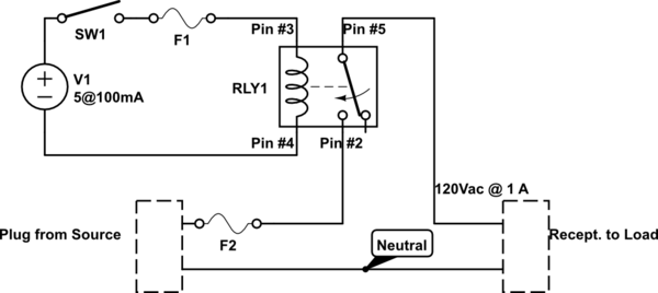
Again, this is my opinion - and that, along with about $3 bucks will get you a large coffee at Starbucks... I'd be happy to provide a wiring diagram if anyone is curious about this.
 

Latest posts

Back
Top