Control Box Build Help

Homebrew Talk - Beer, Wine, Mead, & Cider Brewing Discussion Forum

Help Support Homebrew Talk - Beer, Wine, Mead, & Cider Brewing Discussion Forum:

This site may earn a commission from merchant affiliate links, including eBay, Amazon, and others.

BandonBrewingCo

Well-Known Member
Joined
Apr 6, 2012
Messages
215
Reaction score
72
Location
Innsbruck
Hi,

I want to build a control box for a single vessel system, utilising craftbeerpi. However, my knowledge of electronics is lacking.

According to the wiki what I need is:

  • Raspberry Pi (all models is supported)
  • 1 x 1-wire Temperatursensor DS1820 Waterproof! + Thermowell stainless steel
  • 1 x 4.7k Ohm Resistor
  • Jumper Cable
  • Solid-State Relais XURUI + Heatsink KAB-60 (for each actor you need one relay)

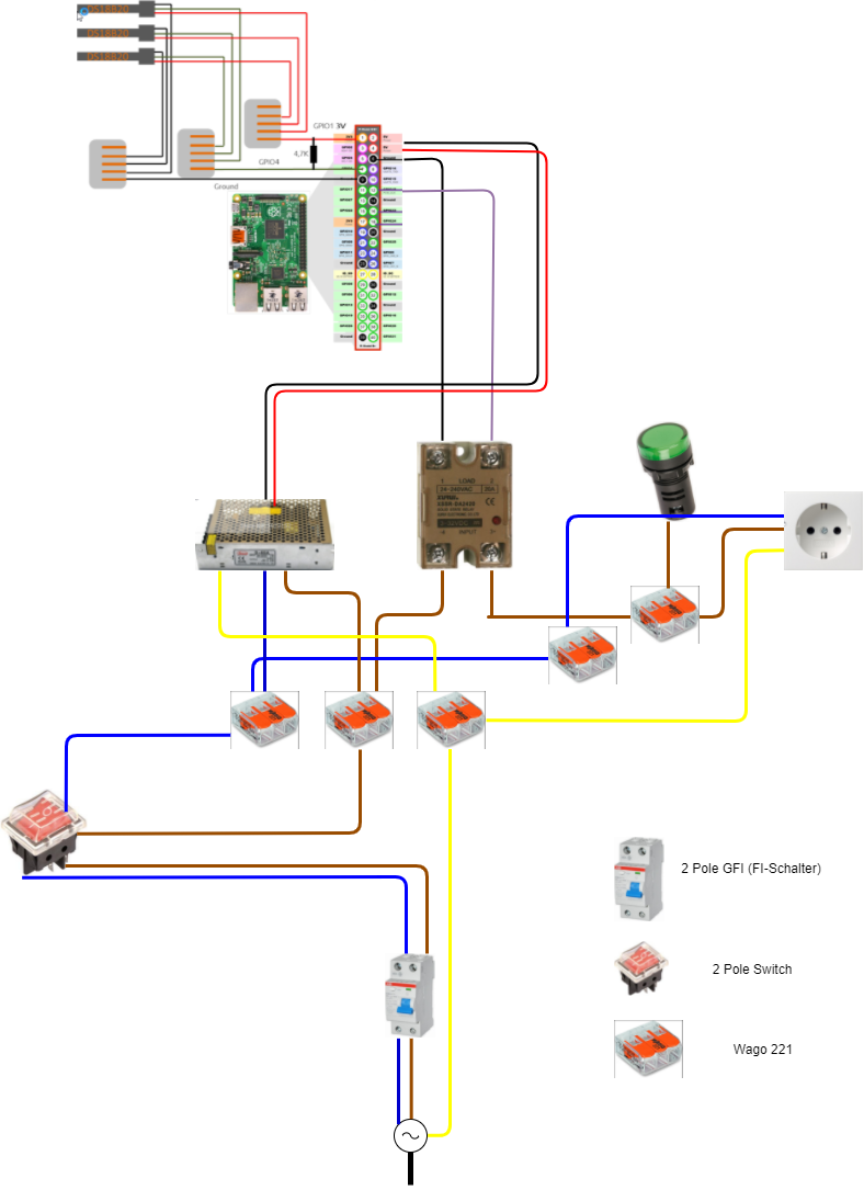
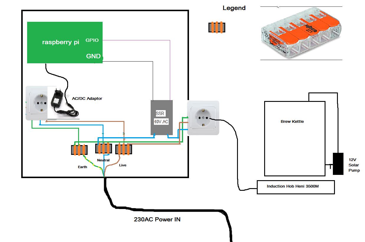
And the wiring looks like this:

wiring.png


Questions:

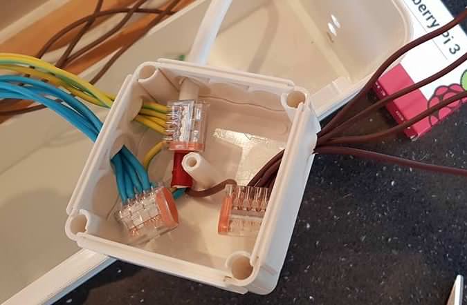
1. What are the grey things with brown stripes on the right hand side? It looks like some sort of thing that takes in one of the 3 mains (European) wires on one side and repeats them out to the SSRs and outputs on the other side. What are these things called? And if they are doing that is each repeating wire carrying up to 240v?


2. Are the ones on the left doing the same thing with pins 1, 7 and 9? Are these the same parts if they are?

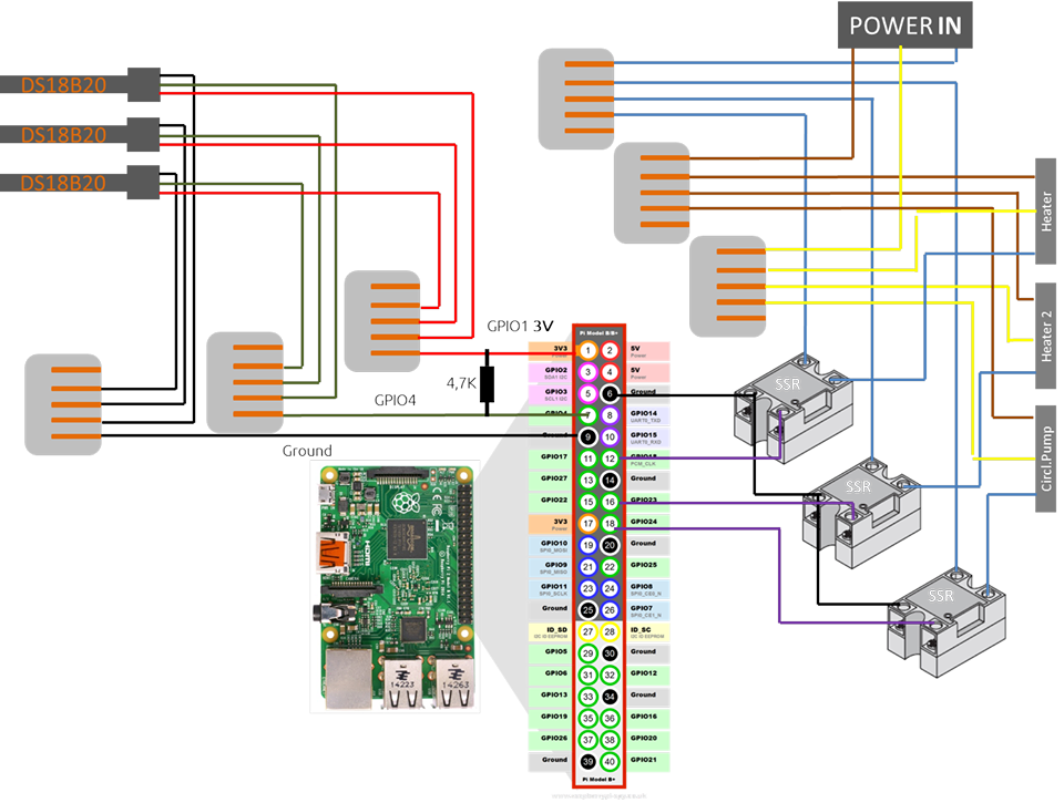
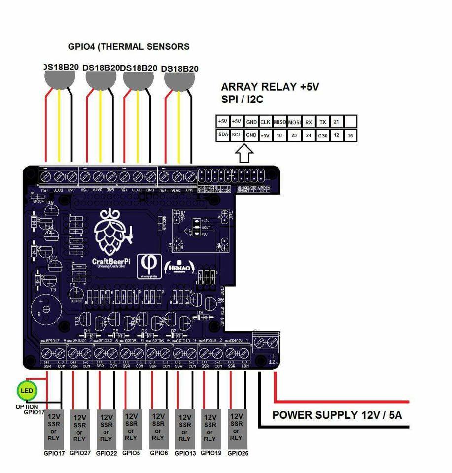
3. What would be the advantage to using the extension board? And where is the third wire for the power supply gone? Also, are the relays on the bottom for SSRs? (I'll be driving a Hendi 3500W Induction Hob).

cbp-shield.jpg


Many thanks!
 
Ok, so it seems the grey thingys with the orange (brown?) stripes are these bad boys:

DXr68Dh.jpg


What are these called? And is each repeater carrying 240v with it?

--------------------------------------------------------------------------------
Disclaimer: No way am I plugging anything in without inspection by a sparky first
 
Ok,
so I think I know now how (Wago 221's ftw) to distribute the power coming in to other devices and for my understanding I've come up with this n00bs diagram

duBuzgF.jpg


  1. Is there anything wrong with this kind of setup?
  2. Do I need a separate power adaptor for the solar pump? Given that I'll be putting a one way ball valve after the pump, is there any reason why I'd want the pi controlling the pump? (For sh1ts and giggles is a perfectly good answer ;))
  3. Do I need to have a mounting/backing plate? And if so, why?

Thanks for your patience :mug:
 
I would have the SSR switching the hot, not the neutral.

The hot side should always be switched rather than the neutral. It's required by electrical code in the USA.

You should also have at least one mechanical switch/contactor on the incoming 230V hot line. SSR's tend to fail in the on mode, so you need a way to shut off the power reliably. SSR's also leak enough to shock you even when they are off, so the mechanical disconnect also protects you from that. 3500W @ 230V is 15.2 A, so the mechanical disconnect switch/contactor needs to be rated for at least 20 A @ 240V.

I also highly recommend 230V AC rated LED lamps be placed in parallel with the SSR switched loads. If these lamps are on or off when they shouldn't be, that means the SSR has failed. Note that the "element firing lamps" can be illuminated when the heating element is not plugged in, but the control panel is powered. This is due to the leakage current of the SSR's.

Edit: You also want to make sure that your 230V AC power input is protected by the European equivalent of a GFCI (Ground Fault Circuit Interrupter) to protect you from electrocution.

Brew on :mug:
 
Last edited:
Thanks Doug, that's a lot of really great information right there! I'll come back with a tidier, safer and more professional schematic.

Regarding the 12V DC part for the raspberry and pump, is there some sort of device that I could send 3 AC wires into and have 2 DC wires come out the other side?

Then I could use the Wago connectors to power the pi and an outlet for the pump. Or can DC not be shared out like AC?
 
is there some sort of device that I could send 3 AC wires into and have 2 DC wires come out the other side?

There are a umber of DC power supplies available. Up to 5A output is pretty reasonable. It starts getting big and expensive above 10A. Here is a link to a 120v example:

Then I could use the Wago connectors to power the pi and an outlet for the pump. Or can DC not be shared out like AC?

DC power can be distributed much like AC power. The main difference is that AC power can travel over much greater distance without voltage drop. DC doesn't travel as well. The further you get from the source of DC power, the larger the wire has to be to carry a given amperage.
 
PS, in most of Europe, L & N are interchangeable as the sockets have no way of setting orientation. So even if I paint a "this side up" on the plug, there's so guarantee the socket will be the same.

Hmmm, then I guess it must be the same for the UK 3 pin as the euro to UK travel adapters don't force orientation either.

How does the ground pin in the plug/socket not force an orientation? You don't want to be plugging one of these control panels into a receptacle that doesn't have a ground pin.

If you indeed have no enforced plug polarization, so can't know for sure which line is hot and which is neutral, then the safest way to get a positive disconnect is to use a double pole switch/contactor, and switch both lines.

Brew on :mug:

I'll have to confirm this with some of the locals. Crazy Germans always up to no good :p

There are two earth pins in the socket and sometimes one or two in the plug

main-qimg-233fbf6fd239491639329d8479675d08


adapter-electric-plug-us-germany-3.jpg
 
Cs6q2lU.png


As you can see, I'm not sure what you mean by putting the LEDs in parallel with the SSR loads? Do you mean the ssr AND it's load be placed in parallel with the bulb?

Are the GFI and 2 pole switcher in correct order and ok?

One more thing, if i have a plastic housing with a metal backing/mounting plate, do I need to earth the housing? I have this one in mind
 
Last edited by a moderator:
Cs6q2lU.png


As you can see, I'm not sure what you mean by putting the LEDs in parallel with the SSR loads? Do you mean the ssr AND it's load be placed in parallel with the bulb?

Are the GFI and 2 pole switcher in correct order and ok?

One more thing, if i have a plastic housing with a metal backing/mounting plate, do I need to earth the housing? I have this one in mind

Here's an example (upper right) of how you connect an LED lamp in parallel with the element (which is the load.)

DSPR120 1 - Element  240V only.PNG

Yes, you have the GFI breaker and main power switch in the correct order.

You don't need to earth anything plastic, but the metal mounting plate should be earthed, as well as the SSR base plate & heatsink. Basically, anything metal that has powered components mounted in/on it should be earthed.

Brew on :mug:
 
Last edited by a moderator:
Thanks again Doug, I really appreciate your help and patience.

Next time I come back will be with an image of actual parts laid out and connected (except the AC of course!)
 
Just getting the last few pieces together...

Am I correct in saying that I need this dual output (12v, 5v) ac/dc :rockin: converter (12v for pump, 5v for pi) and this stepdown buck to drop the 5v 6A down to 5v 3A for the pi?

Also, the 12V solar pumps are rated at max 0.5A... do I need another stepdown for this as the dc converter is giving out 4A at 12V, or are the pumps not as sensitive to a power surge as the pi is?

Thanks again!

You don't need to reduce the current capability of the power supply for either case. The Amp rating is just the maximum that the power supply can output while maintaining the specified voltage. You actually want the power supply to be rated for slightly more A then you think you need.The Pi and the pump will only draw as much current as they actually need.

Brew on :mug:
 
Ah. So people are only using the stepdown modules to step down from 12v to 5v?

The power supply you have selected converts the AC line voltage to both a 12V output and a second 5V output. There is no need for any other DC power supply components.

Edit: You might use a step-down power supply if your primary DC supply only provided 12V. You could then generate 5V from the 12V supply with the step-down power supply. But, you don't need that, since you already will have both voltages available from the primary power supply.

Brew on :mug:
 
Last edited:

Latest posts

Back
Top