Circuit Verification

Homebrew Talk - Beer, Wine, Mead, & Cider Brewing Discussion Forum

Help Support Homebrew Talk - Beer, Wine, Mead, & Cider Brewing Discussion Forum:

This site may earn a commission from merchant affiliate links, including eBay, Amazon, and others.

tmyoung

Member
Joined
Mar 30, 2012
Messages
19
Reaction score
1
Location
Portland
Hey guys,

If anyone would be so kind as to take a look, I'm hoping to get feedback on my circuit diagram. I'm feeling fairly confident about it, but this is not an area where I want to screw around. The system will be a small counter top system very similar to jkarp's. My control box will have (2) 20 Amp conventional single socket outlets on the bottom where heater element and pump will plug in. The switches will be basic on/off toggle switches which are rated for 15 amp. I only have 15 amp outlets in my apartment, so I am thinking I should fuse my box with a 15 amp fuse as a fail safe. However, I'm wiring the box for 20 amps, so I could switch out the elements if I have access to more juice. Please excuse my made up circuit symbols.

Thanks for any input.

View attachment S25C-115033012420.pdf
 
Last edited:
What size heating element are you wanting to use? If you'r wiring for 20amps you should probably use 20amp switches and components too.

You got some crazy business going on in the relay portion of your schematic. You want your relay and heating element in series, not parallel. Take a look at this:

Auberin-wiring1-a4-2000w-BIAB-120V-A.jpg
 
Thanks for sharing the diagram. The plan is to run 1500 Watt element, until I can move somewhere with 20 Amp sockets, at that point I will change out for a 2000 Watt element. I intend to place one 15 amp toggle switch inline with the pump circuit, and the other between the PID and the SSR. If I understand correctly, those toggle switches will never see 15 Amps.

Related question - I was just planning on soldering all of the wire together and wrapping in heat shrink tubing. Looking at the figure with the nice looking junctions boxes, I'm thinking that may not be advisable. Is that correct?
 
I don't know if there is a specific reason for it, or if it is just convention, but I don't think I've ever seen mains power wiring soldered. I can think of a couple of reasons why I wouldn't want to solder it.

Everything I've seen uses wire nuts, even the commercially preassembled stuff.
 
Thanks for sharing the diagram. The plan is to run 1500 Watt element, until I can move somewhere with 20 Amp sockets, at that point I will change out for a 2000 Watt element. I intend to place one 15 amp toggle switch inline with the pump circuit, and the other between the PID and the SSR. If I understand correctly, those toggle switches will never see 15 Amps.

2000 watt element / 120 volts = 16.7 amps at your element toggle switch. If you plan on swapping out elements you better swap out the switch too.

I'd recommend investing in some ratcheting wire crimpers, stranded wire and crimp terminals make these jobs so much nicer.

Crimpers
Toggle Switches
Any kind of switch you could imagine
 
Last edited by a moderator:
2000 watt element / 120 volts = 16.7 amps at your element toggle switch. If you plan on swapping out elements you better swap out the switch too.

I'd recommend investing in some ratcheting wire crimpers, stranded wire and crimp terminals make these jobs so much nicer.

Crimpers
Toggle Switches
Any kind of switch you could imagine

Unless the switch is powered at low voltage to the coils of a contactor, of course. That is what I would recommend, sizing the xontactor fir a 20a load.
 
Last edited by a moderator:
My idea was to place the switch between the PID and the relay that controls the element. There is no way the PID will have more than 15 Amp output, the PID is fused at 0.75 Amp.
 
My idea was to place the switch between the PID and the relay that controls the element. There is no way the PID will have more than 15 Amp output, the PID is fused at 0.75 Amp.

Ok, but when SSR's fail, they fail in the closed position allowing the current to flow. Having a US$10 contactor in place would give you the ability to completely shut off the electricity to the element. While I trust the switch to not send a control signal from the PID to the SSR when the switch is open, when the SSR fails closed (most of the time when they fail it's closed) it doesn't matter what signal the PID is sending.

Follow?
 
Last edited:
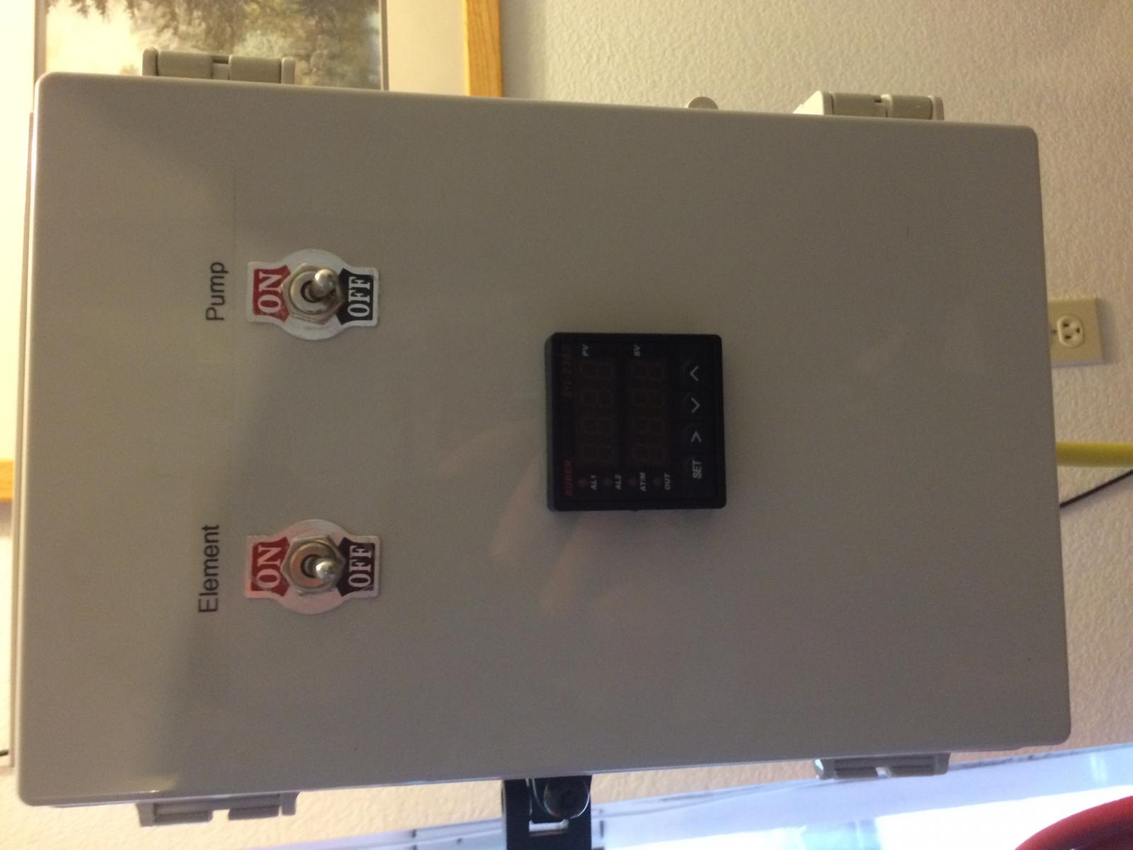
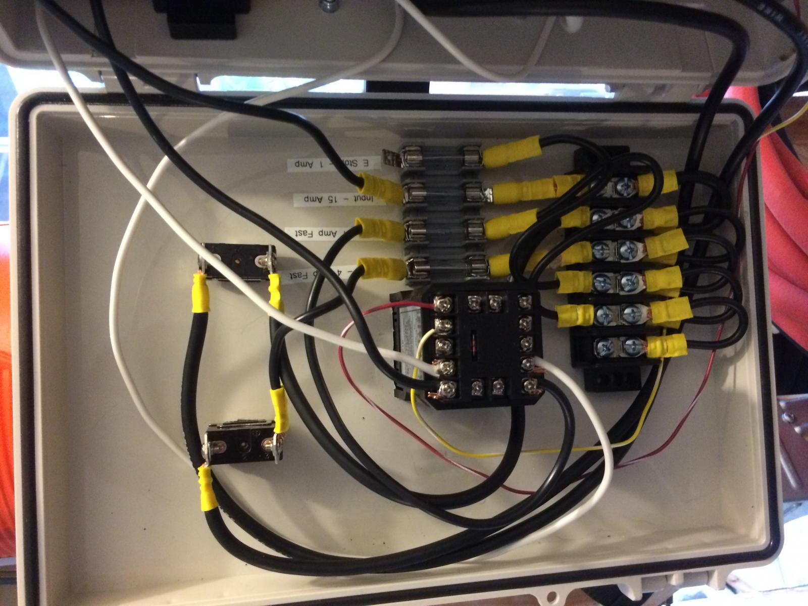
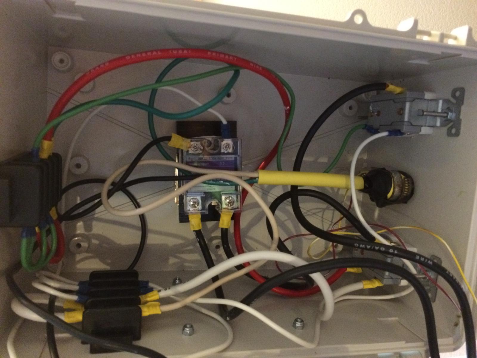
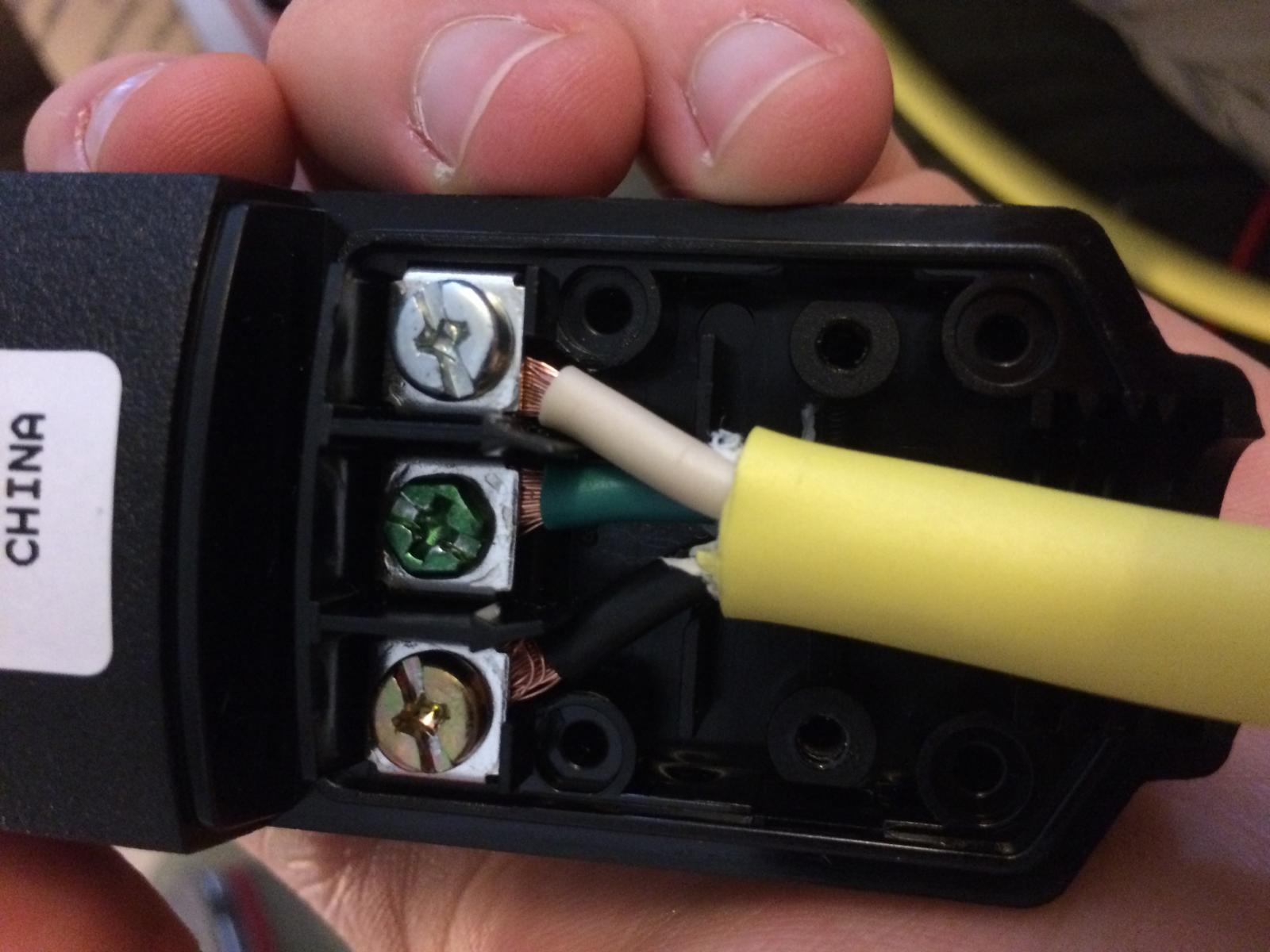
I had to put the project on hold so I could finish up grad school. I follow on that last post before I dropped off I wired the switch just as in the wiring diagram, but with the 15 Amp switch. Its not in the pictures, but I've put a note to self in the box to remind myself to up-rate the switch if I convert the box to a 2000 Watt element.

I started soldering the connections, but it is difficult to solder the 10 gauge wire, so I made the capital investment in ratcheting crimpers and big boxes of connectors.

Considering my kitchen is wired for 15 Amp current (12 gauge Nomex), but the breaker is 20 Amp, am I safe running my 15 Amp system? Do I need to make sure I'm not running any small appliances during my brew?

Thanks for all the guidance.

IMG_4211.jpg


IMG_4209.jpg


IMG_4210.jpg


IMG_4207.jpg
 
Someone correct me if I'm wrong but I believe 12 awg wire is good for 20 amps.

I'll assume though that your power receptacles are 15 amp? The one in the background on the first picture appears to be 15 amp. Don't exceed current draw of the rating of the lowest rated component in the whole circuit. Also your not supposed to exceed 80% of that current load for more than a couple hours at a time.

#12 is good for 20 amps. it is acceptable to place 15 amp or 20 amp receptacles on a 20 amp circuit (#12 wire protected by a 20 amp circuit breaker). it is acceptable to place #12 wire on a 15 amp circuit breaker but receptacles on such a circuit would be limited to the 15 amp type.

note that if there is only a SINGLE receptacle on a circuit, it must be rated no less than the rating of the circuit. a single receptacle on a 20 amp circuit would need to be rated 20 amp; a single 15 amp receptacle would not be acceptable.

above is based on the nec, other codes may differ.
 
I made a typo - the wiring behind the sockets is the white Romex, which is 14 gauge wire rated for 15 Amps, but the breaker is a 20 Amp breaker. My 1500 Watt element should draw around 12.5 Amps (about 83% of the 15 Amp socket), so as long as I can come to a boil in under a couple of hours I should be okay. I am curious what the draw is on all of the other non-brewing ancillaries that run in the kitchen is. I suppose a couple of lightbulbs is only an amp or two?

Thanks for the input.
 
#14 on a 20 amp breaker is a code violation. i'm not saying you have a ticking time bomb on your hands but there is certainly a risk of overloading the cable and potentially causing a fire. proceed with caution...
 
Ok, but when SSR's fail, they fail in the closed position allowing the current to flow. Having a US$10 contactor in place would give you the ability to completely shut off the electricity to the element. While I trust the switch to not send a control signal from the PID to the SSR when the switch is open, when the SSR fails closed (most of the time when they fail it's closed) it doesn't matter what signal the PID is sending.

Follow?

Only hijacking a bit here, but have a question related to this. For a 15a system, are contactors really necessary? There are plenty of switch options for 15a and even 20a. Why add the complication of a contactor?
 
#14 on a 20 amp breaker is a code violation. i'm not saying you have a ticking time bomb on your hands but there is certainly a risk of overloading the cable and potentially causing a fire. proceed with caution...

I've come to learn that the apartment I live in was built by criminals. I'm a structural engineer, and I've done some work for the owner to address some structural issues. Through my involvement in his projects, I've learned that there is shoddy workmanship in almost every aspect of this building. I'll bet I have a nearby circuit available with 14 gauge wire, and a 15 Amp breaker, that is probably the obvious solution. It would be nice to know what else is going on in the walls.

Only hijacking a bit here, but have a question related to this. For a 15a system, are contactors really necessary? There are plenty of switch options for 15a and even 20a. Why add the complication of a contactor?

I'm afraid I can't answer that, my system was inspired by jkarp's countertop Brutus 20 system, and he used a relay, so I did too.
 
Only hijacking a bit here, but have a question related to this. For a 15a system, are contactors really necessary? There are plenty of switch options for 15a and even 20a. Why add the complication of a contactor?

Na. As long as your switch is rated for it go for it. The contactor is only necessary when we start getting into higher amperage circuits that typical panel switches can't handle, its a relay for your relay... For a 15 amp circuit you can probably just use some wall light switches from your local big box store.
 
Na. As long as your switch is rated for it go for it. The contactor is only necessary when we start getting into higher amperage circuits that typical panel switches can't handle, its a relay for your relay... For a 15 amp circuit you can probably just use some wall light switches from your local big box store.

Agree. I have a bare bones 120v control panel for my small batch ebiab rig. There are plenty of switch options good for up to 20A.
 

Latest posts

Back
Top