BruControl: Brewery control & automation software

Homebrew Talk - Beer, Wine, Mead, & Cider Brewing Discussion Forum

Help Support Homebrew Talk - Beer, Wine, Mead, & Cider Brewing Discussion Forum:

This site may earn a commission from merchant affiliate links, including eBay, Amazon, and others.
I haven't looked to see what Futaba et al have for full rotation servos wrt torque ratings these days, but frankly a hop adder would be better implemented using a stepper motor, which are definitely available (and have been used with BC)...

Cheers!

Indeed!

 
I would say no, pretty soon you will be able start and complete a brew while on vacation. :p But this is from someone who is still at the point and click stage, and not a single script in sight. :no:

If/when I tackle grain delivery to mill and to mash tun, then I could start a beer on vacation and when I get home it could be kegged and ready to drink.
Right now I would have to start it the day of vacation since I need to load grain. Everything else I have done now. :)

I routinely brew from work now.
nUkU1Yt.png
 
Incredible!!

One learning @Die_Beerery uncovered in all this script creation is an important lesson: you should not name an element by a number. The reason is a script will reference element names prior to evaluating values. Specifically, if you say a variable equals a value, and that value is the name of a button, the script will error because it’s looking for a property of that value (or name in this context). For example, if you have a button named "7", and ran the following script, it will fail because the interpreter looks for the property of 7 (as if it were 7 State)

Code:
new value beer
beer = 7

Hope this makes sense. If not, its simple: Don't name elements using numbers only. Use names with letters in them, so above should be "Button_7" instead.
 
The resulting value from the device will be in degrees C. Add a calibration to convert it to F. Edit: See @clearwaterbrewer's response above - much better than mine!

The ES boards are Active High, so leave the “Active Low” switch off. You can run them active low, but the state will be reversed (active = ON = low voltage = relay off).
Check out that PDF Link regarding RTDs I sent. It has that info in it on how to convert.
 
Does anyone use a Proportional valve with a PWM Output to control propane? If so, what specific valve? I am thinking that I could reduce my boil automatically based on time or temperature once I have a roiling boil. We now adjust manually but my "controller" got distracted and we boiled from 13 to 6.6 gals for an 11 gal brew last week in 90 minutes.
 
Does anyone use a Proportional valve with a PWM Output to control propane? If so, what specific valve? I am thinking that I could reduce my boil automatically based on time or temperature once I have a roiling boil. We now adjust manually but my "controller" got distracted and we boiled from 13 to 6.6 gals for an 11 gal brew last week in 90 minutes.
It's been a while since I used propane/ng, but I'm not sure that a proportional valve would give you the level of control you would be looking for. If it were me, I would create two gas paths to the burner that would be hard set with needle valves to effectively give me high (both paths), medium (1 higher flow) and low (1 low flow). Solenoids could easily control the gas path and you could have a program cycle between them during the course of your boil.
 
OK, got my 2nd RTD box built, sorry about screwing through your logo, @BrunDog ;-) One is still on the Mega, waiting to figure out how to hook up the MOSI/MISO/CLK to the ESP32 correctly..

The other was to see how well it worked on CBP3, you can see the pi stuffed in there... it worked, but was slow, and the Pi was picky when it came to max boards, one that works fine on the mega did not work on Pi... wouldn't actually be used in a brewing environment, probably just operating a Heat exchanger setup or a fermenting setup, and using MQTT to run SonOff smartplugs...
IMG_20190904_162602.jpg
IMG_20190904_162644.jpg
 
Shot through the logo! Doh!

Cool stuff. I owe you the SPI pins. I will get it tested in the next day or two!


Thank you! If you run out of boards and make another batch, I would suggest a size smaller on the screw terminals, I have to crimp ends on to normal jumpers(30ga??) to get the terminals to grab.

Side thought... I think I could put another RP-3 board underneath this one, but it would have to be at a 90 degree angle, some accurate standoffs could make it proper, then could have 4 probes on each side. 8 RTDs in one waterproof and wifi capable box, which would be awesome for off-the shelf components...
 
I am willing to bet that inside the servo, that PWM is converted to an analog level with a simple RC filter.. If you have a servo, why not give it a shot?

People ARE using the Mega to control servos, so it is not like it is going to damage either device...

I tried this just now and it does not work. Setting the output to anything but 0 would make the servo rotate by a few degrees, seemingly independent of the set value, and keep buzzing until value set back to 0, at which point it would return to original position and stop buzzing.
 
Pg 41 from the manual. "Digital Output These are binary devices which command the interface’s pin to be a high or low voltage. These types of devices are noted above under Device Types, list #1. The state is presented as the Element’s state and will either be ON or OFF depending if the voltage is high or low. High is ~90% and low is ~10% of the interface’s operating voltage (approximate values, depends on the interface’s CPU). By default, when the Device Element is ON, the interface pin’s voltage is high (Active High)."

ELECTRONICS-SALON DIN Rail Mount 8 SPDT Power Relay Interface Module, 10A Relay, 12V Coil

Manufacturers Spec:
Operating Voltage/Current(max.): 12Vdc / 400mA.
Input control signal voltage:
0V - 0.5Vdc, low level, relay not action.
0.5V - 2.5Vdc, unknown state.
2.5V - 24Vdc, high level, relay action.
Input control signal high level current:
2.5V: 0.1mA.
5V: 0.35mA.
12V: 1.1mA.
20V: 1.9mA.

I use the 5VDC Coil version of this relay board and the inputs work fine with "Active Low". (ON)
If you are going to be using SSR's in your build you will need to determine the control signal voltage requirement as per manufactures recommendation.
So pretty much a yes or a no but the no actually has a bit of voltage?

google is your friend, and also the adafruit page on the RTD amplifier board has info and pics on the reference resisto.. Also, you need to have soldered your jumpers correctly, and best to have checked continuity and non-continuity with a meter, as the one trace that you have to break can look broken but still conduct, and you will wonder what is wrong.

In BC:
1 - you add the 'Resistance Temperature RTD' calibration and enter the calibration resistor on the board (usually 430)
2 - you add the Celsius to Fahrenheit calibration (scroll down)
3 - add a decimal point or two
4 - add a F in the suffix box...
I try to use google but I'm green AF. Not even sure how to form the question most of the time. Thankyou for sharing the info regarding the amplifiers. I didnt realize there was more work to do to these. The scope makes sense and I can solder, no issues here. Ill ensure continuity and non continuity where applicable. Thanks

The resulting value from the device will be in degrees C. Add a calibration to convert it to F. Edit: See @clearwaterbrewer's response above - much better than mine!

The ES boards are Active High, so leave the “Active Low” switch off. You can run them active low, but the state will be reversed (active = ON = low voltage = relay off).
Got it! Will do. I thought I saw these instructions somewhere in a video but couldnt seem to find it. So, If i understand correctly, active high is like NC and active low is like NO but since this both actually carry voltage, this is a poor choice of naming?
 
We are indeed shifting to smaller screw terminals. Just completed the design for an updated thermistor filter board which will go to surface mount to be smaller and accommodate 8 probes. We’ll take a stab at the platform but haven’t solved the packaging improvement yet.
 
So I dove into learning scripting today/yesterday. I was able to make a button start and reset a timer as well as make a fake thermostat to change GUI.

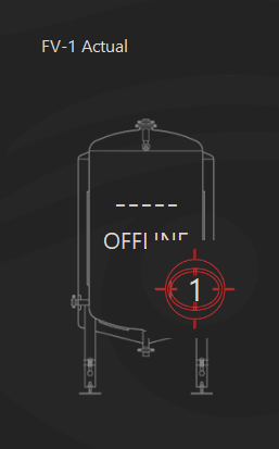
I then attempted the following script to cycle between three background images of SPI sensor. I’m having an issue with the a switch I define "Cold Crash". Currently the graphics are feverishly cycling through background 3 and 1 or 2. What am i missing here?

[start]
[loop]
if "FV-1 Active" State == OFF
"FV-1 Actual" Background = 1
else "FV-1 Active" State == OFF
"FV-1 Actual" Background = 2
endif
if "Cold Crash" State == ON //having an issue here stabilizing background
"FV-1 Actual" Background = 3
endif
goto "loop"
 
Last edited:
So I dove into learning scripting today/yesterday. I was able to make a button start and reset a timer as well as make a fake thermostat to change GUI.

I then attempted the following script to cycle between three background images of SPI sensor. I’m having an issue with the a switch I define "Cold Crash". Currently the graphics are feverishly cycling through background 3 and 1 or 2. What am i missing here?

[start]
[loop]
if "FV-1 Active" State == OFF
"FV-1 Actual" Background = 1
else "FV-1 Active" State == OFF
"FV-1 Actual" Background = 2
endif
if "Cold Crash" State == ON //having an issue here stabilizing background
"FV-1 Actual" Background = 3
endif
goto "loop"

No scripting expert, but it looks like you have a loop with no delays in the restart of that loop, so it's just cycling through the loop over and over as fast as the computer can think, and that's why you're seeing the images feverishly change.

You can add a delay in the loop to delay the restart of the loop. 'Sleep 5000' will give a 5 second delay.
 
So pretty much a yes or a no but the no actually has a bit of voltage?

Short answer is yes, I'm guessing here but they added "Unknown State" dependent on which interface is used to drive it. As mentioned both states will work, it's just how the input receives the signal. As @BrunDog mentions above on "Active Low" the states are reversed but I use LED buttons as indicators and wired my relays accordingly so it's a none issue for me.
 
Last edited:
So I dove into learning scripting today/yesterday. I was able to make a button start and reset a timer as well as make a fake thermostat to change GUI.

I then attempted the following script to cycle between three background images of SPI sensor. I’m having an issue with the a switch I define "Cold Crash". Currently the graphics are feverishly cycling through background 3 and 1 or 2. What am i missing here?

[start]
[loop]
if "FV-1 Active" State == OFF
"FV-1 Actual" Background = 1
else "FV-1 Active" State == OFF
"FV-1 Actual" Background = 2
endif
if "Cold Crash" State == ON //having an issue here stabilizing background
"FV-1 Actual" Background = 3
endif
goto "loop"


[start]
[loop]

if "FV-1 Active" State == OFF
"FV-1 Actual" Background = 1
else "FV-1 Active" State == OFF
"FV-1 Actual" Background = 2
endif

if "Cold Crash" State == ON
"FV-1 Actual" Background = 3
endif

sleep 1000
goto loop


I code like this with indents and spaces, for me it allows me to easily parse the data. Anywho, the bold section should fix it for you assuming those are all elements.
edit: looks like it didn't do my indent formatting.
 
Last edited:
Oh, that was using the ESP32 not the MEGA. Not sure that makes a difference.
well, that is 3.3v, not 5v, so could be an issue also... if it were just the voltage issue, I would say it probably is the same as the Mega.. but it is not just the voltage...

A simple search on: ESP32 servo brings up this result that states: "Interfacing a servo motor to the ESP32 is very difficult compared to an Arduino, since it does not support analogWrite(). However, it uses various frequencies and timers, allowing the all digital pins to be used as PWM pins as well send signals significantly faster than any Arduino"
 
Last edited:
[start]
[loop]

if "FV-1 Active" State == OFF
"FV-1 Actual" Background = 1
else "FV-1 Active" State == OFF
"FV-1 Actual" Background = 2
endif

if "Cold Crash" State == ON
"FV-1 Actual" Background = 3
endif

sleep 1000
goto loop


I code like this with indents and spaces, for me it allows me to easily parse the data. Anywho, the bold section should fix it for you assuming those are all elements.
edit: looks like it didn't do my indent formatting.

The reason for the changes is you don’t have exclusivity in the comparisons. This means you will get one image selected from the first if block and another image in the second if block if the “Cold Crash” State is indeed on. Adding the time delay won’t stop the image flip-flopping but it will slow it down.

Here is a way to solve this by nesting the if blocks. This assume you want the second or third image only if the “FV-1 Active” State is off. If not, you can change it as needed.

Code:
][start]
[loop]

if "FV-1 Active" State == ON
"FV-1 Actual" Background = 1
else  // removed the rest since if it’s not ON it can only be OFF
if "Cold Crash" State == ON 
"FV-1 Actual" Background = 3
else
"FV-1 Actual" Background = 2
endif
endif
sleep 1000
goto loop
 
OK, got my 2nd RTD box built, sorry about screwing through your logo, @BrunDog ;-) One is still on the Mega, waiting to figure out how to hook up the MOSI/MISO/CLK to the ESP32 correctly..

The other was to see how well it worked on CBP3, you can see the pi stuffed in there... it worked, but was slow, and the Pi was picky when it came to max boards, one that works fine on the mega did not work on Pi... wouldn't actually be used in a brewing environment, probably just operating a Heat exchanger setup or a fermenting setup, and using MQTT to run SonOff smartplugs...
View attachment 642894 View attachment 642895
Purple Max 31865s???
 
Sleep 5000' will give a 5 second delay.

sleep 1000

sleep 1000
[/CODE]

Got it to work with BrunDogs fix. So the sleep just calms the computer down? Is 1000 used as a rule of thumb?

On a side note, I'm having trouble stacking multiple elements that utilize images with transparent backgrounds. I suspect it to preserve transparency throughout the various layers but it is not behaving correctly. My goal here is to rely on stacked elements with varying graphics rather then scripting to change background across various states.

I will note, the elements (unstacked) are utilizing the transparency from stock image beautifully.

Tr.png


It appears some other users are relying on backgrounds to house the various blocks.. As the project grows and becomes more complex, I see this being a non fluid approach to the interface as you may find yourself constantly going to and from graphics software back to BC. I propose a feature request: To allow stacked elements (preserving transparency) to link to each other allowing user to move a group of elements simultaneously across a clean background, thus not rely on a fixed background to set the elements. Very similar to how layers work within Photoshop.

lock.png

So layer 1 and 2 are linked together via the link button. When Layer one is moved so is Layer two. Layer three and Background will remain independent.

Perhaps this is possible already?
 
well, that is 3.3v, not 5v, so could be an issue also... if it were just the voltage issue, I would say it probably is the same as the Mega.. but it is not just the voltage...

A simple search on: ESP32 servo brings up this result that states: "Interfacing a servo motor to the ESP32 is very difficult compared to an Arduino, since it does not support analogWrite(). However, it uses various frequencies and timers, allowing the all digital pins to be used as PWM pins as well send signals significantly faster than any Arduino"

Ok. So I tried with the mega. Also didn't work. Same behavior as with the ESP32.

Brundog, to do this, I had to look for an available pin on the mega to create a new PWM element. My only available pin with this capability was 10. According to the wiring map, with a serial connection, PWM should be an option for 10 but it was not... Maybe the map is incorrect?

I ended up disconnecting my proportional valve for this experiment.
 
Your computer, depending on its relative processing power, will have the script interpreter work through script lines on the order of tens of thousands per second. Since there is no need for that to happen since our "slow" human world cant do anything with the information that fast anyway, its good practice to add a delay so the script "goes to sleep" and free's up the CPU to do other stuff. So there is no hard & fast rule - you set it for the response rate you need, and nothing faster.

Please email us the images you are using - we'll test them to see if we can make the transparency work through the elements. To your other comment, we are adding a graphic-only element which can handle animations too, so you can call upon screen elements to do things such as show running liquid graphically, etc. Regarding the element grouping - that's a great idea. We'll take a look.
 
Please email us the images you are using - we'll test them to see if we can make the transparency work through the elements. To your other comment, we are adding a graphic-only element which can handle animations too, so you can call upon screen elements to do things such as show running liquid graphically, etc. Regarding the element grouping - that's a great idea. We'll take a look.
Email sent, let me know if you need anything else.
 
The reason for the changes is you don’t have exclusivity in the comparisons. This means you will get one image selected from the first if block and another image in the second if block if the “Cold Crash” State is indeed on. Adding the time delay won’t stop the image flip-flopping but it will slow it down.

Here is a way to solve this by nesting the if blocks. This assume you want the second or third image only if the “FV-1 Active” State is off. If not, you can change it as needed.

Code:
][start]
[loop]

if "FV-1 Active" State == ON
"FV-1 Actual" Background = 1
else  // removed the rest since if it’s not ON it can only be OFF
if "Cold Crash" State == ON
"FV-1 Actual" Background = 3
else
"FV-1 Actual" Background = 2
endif
endif
sleep 1000
goto loop


this in general is a GREAT tip to all if - else usage... I suggest something like this in the script section of the manual... Really useful to anyone looking to do scripts for any reason. Also suggest to specifically point out that 'elseif' is not supported..
 
Ok. So I tried with the mega. Also didn't work. Same behavior as with the ESP32.

Brundog, to do this, I had to look for an available pin on the mega to create a new PWM element. My only available pin with this capability was 10. According to the wiring map, with a serial connection, PWM should be an option for 10 but it was not... Maybe the map is incorrect?

I ended up disconnecting my proportional valve for this experiment.

I see the problem... it is in the interface definition file. PM me your email and I will send you a corrected one. Otherwise, if you are comfortable editing xml files, it is under the Serial / default interface definition. You can see port 9 and 11 include PWM but 10 does not - need to add that line there.
 
I have setup this code to heat my Big Mac HLT.

It is a 5500 w 220vac element.

I have it hooked up via an mechanical Electrical Contactor so that both hots are "broken" when off.
The BigMac is a Digital Out that send a trigger to an SSR that has 24vac on the load side to run the Electrical Contactor
In the BCS I used Hysteresis with a swing of 4. I think I have accomplished the same thing with this code.


Anyone see any issues with this?
It seems to work in theory and does not throw any errors.

I noticed that the Hysteresis Device Element does not have a reversed property so I cannot use that for heating??

I added the sleep command because BruControl kept locking up with two continuous script loop running at the same time.

//Heat the Big Mac
// Declare variables
new value vVBTarget
new value vVBMTemp
new value vVHighSide
new value vVLowSide
"BigMac" enabled = true
[HeatBM]
sleep 1000
vVBTarget = BMTarget value
vVHighSide = vVBTarget + 2
vVLowSide = vVBTarget - 2
vVBMTemp = "BigMacProbe" value
if vVBMTemp >= vVHighSide
"BigMac" state = false
endif
if vVBMTemp <= vVLowSide
"BigMac" state = True
endif
goto HeatBM
 
RTFM. Hysteresis can do both cooling and heating. It is explained quite clearly in the manual. You have to set the on offset to a negative number.
I have setup this code to heat my Big Mac HLT.

It is a 5500 w 220vac element.

I have it hooked up via an mechanical Electrical Contactor so that both hots are "broken" when off.
The BigMac is a Digital Out that send a trigger to an SSR that has 24vac on the load side to run the Electrical Contactor
In the BCS I used Hysteresis with a swing of 4. I think I have accomplished the same thing with this code.


Anyone see any issues with this?
It seems to work in theory and does not throw any errors.

I noticed that the Hysteresis Device Element does not have a reversed property so I cannot use that for heating??

I added the sleep command because BruControl kept locking up with two continuous script loop running at the same time.

//Heat the Big Mac
// Declare variables
new value vVBTarget
new value vVBMTemp
new value vVHighSide
new value vVLowSide
"BigMac" enabled = true
[HeatBM]
sleep 1000
vVBTarget = BMTarget value
vVHighSide = vVBTarget + 2
vVLowSide = vVBTarget - 2
vVBMTemp = "BigMacProbe" value
if vVBMTemp >= vVHighSide
"BigMac" state = false
endif
if vVBMTemp <= vVLowSide
"BigMac" state = True
endif
goto HeatBM
 
I have an inspector that I'm using to display the Total of a counter. I have a script that runs in the background that does a bunch of housekeeping stuff, and I just added two variables to that to reference with an inspector.

Code:
new value BKFlowTotal
new value MTFlowTotal

BKFlowTotal = BK_Flow Total
MTFlowTotal = MT_Flow Total

and the inspectors displays BKFlowTotal and MTFlowTotal. The problem is that these two values are three decimal places, and I would like to only have 1. More specifically, they have 4 decimal places of information but it just seems to show 3. There doesn't seem to be a way in the inspector to tell it to only do 1 decimal place, and there doesn't appear to be a rounding function in the scripting language. So when the (calibrated) counter Total is 2.4601 and I have the inspector show 3 digits, I get "601".

For example, it would be nice to be able to do

Code:
new value BKFlowTotal

BKFlowTotal = BK_Flow Total
BKFlowTotal *= 10
BKFlowTotal = round BKFlowTotal
BKFlowTotal /= 10

I tried changing the number of digits that it shows in the Counter Calibration tab, but that doesn't seem to change the data that it spits out.

Am I missing something? I can't think of a way to easily make it less digits with the current toolbox.
 
Somehow that escaped me when I was trolling through the manual trying to figure out what I was missing. I knew it had to be simple.

Thanks!
 
Thank you! If you run out of boards and make another batch, I would suggest a size smaller on the screw terminals, I have to crimp ends on to normal jumpers(30ga??) to get the terminals to grab.

Side thought... I think I could put another RP-3 board underneath this one, but it would have to be at a 90 degree angle, some accurate standoffs could make it proper, then could have 4 probes on each side. 8 RTDs in one waterproof and wifi capable box, which would be awesome for off-the shelf components...

Tested the ESP32... its not working. But you knew that. We'll need to put some time in to see why. BTW we used the VSPI pins... 5, 18, 19.
 
Back
Top