BruControl: Brewery control & automation software

Homebrew Talk - Beer, Wine, Mead, & Cider Brewing Discussion Forum

Help Support Homebrew Talk - Beer, Wine, Mead, & Cider Brewing Discussion Forum:

This site may earn a commission from merchant affiliate links, including eBay, Amazon, and others.
To be clear, I'm not married to the Google sheets approach. I'd there's another easier way to access the data remotely I'm open to alternatives

yes... Just use BC to graph the pressure sensor and the tilt hydrometer. Now, granted, if you want temperature also, you will need 2 graphs since BC can only graph 2 elements per graph (just for now, I hope)
 
The above is a reasonable plan. Here's a challenge I'm facing now. I bought the HiLetgo ESP32 that others have discussed in this thread and set it up yesterday. My challenge is that it is struggling to get the signal from the Tilts. I now ferment under pressure in kegs. Obviously the BT signal probably is impacted by the kegs but my phone picks up the signal reliably within a couple feet. I also have a pi zero setup and it has been extremely reliable anywhere inside the chest freezer. I was able to get a signal through the ESP32 if I put it right on top of the keg... But even then, signal dropped after a few minutes and never picked it up again.

So... Is it worth trying another one? Could there be variation from board to board? Is there another model folks might recommend?

I'm assuming there's no such thing as a device that would pick up the signal, amplify it and repeat it, right?
 
I'm assuming there's no such thing as a device that would pick up the signal, amplify it and repeat it, right?

I had the same issue with my BrewHaHa BIAC conical. I would expect similar results from any SS FV due to the Faraday cage created by the metal enclosure. I think rather than looking for amplification you should consider a better antenna (than the one built into the printed circuit on your interface.)

I haven't done it yet, but my plan once I get my brewery up and running again is to build a highly directional antenna to point at my FV. I'm thinking of something like this Sparkfun article.
 
Here is a question on the new firmware (v45).

I am using an esp8266 to control a power outlet. The setup is pretty simple, there are two float switches, a 2 relay board, and the esp8266. There is a pump is in a bucket and when it fills to the top float switch the pump turns on and runs until the lower float switch trips. Both of the float switches are configured to short to GND when closed.

When I configured GPIO13 and GPIO14 as digital inputs that are active low, there did not appear to be any internal pull up resistor active on the pins. The pin voltage reads 0V with a DMM with the pin floating. I tried GPIO4 as well and again, no pull up. If I read the documents about the esp8266 correctly, it should support this function, so I'm curious if there might be a bug in the v45 firmware?

Is there any other reason you can think of that the pull ups wouldn't be enabled?
 
I had the same issue with my BrewHaHa BIAC conical. I would expect similar results from any SS FV due to the Faraday cage created by the metal enclosure. I think rather than looking for amplification you should consider a better antenna (than the one built into the printed circuit on your interface.)

I haven't done it yet, but my plan once I get my brewery up and running again is to build a highly directional antenna to point at my FV. I'm thinking of something like this Sparkfun article.

I like the idea of more sensitive antenna (obviously because my other devices work, a more sensitive antenna could work). Are there ESP32 boards with better antennas? or boards to which I can plug in an external antenna? I'll look into, but I'm skeptical of my ability to hack into this board and add a DIY antenna... seems like I would need pretty specific instructions.
 
Obviously I don't know what I'm talking about... Is there not a way to use the pi or some other device that had a better antenna and use that to output some analog or digital signal that the mega could interpret? Forgive me if that doesn't make any sense...
 
Here is a question on the new firmware (v45).

I am using an esp8266 to control a power outlet. The setup is pretty simple, there are two float switches, a 2 relay board, and the esp8266. There is a pump is in a bucket and when it fills to the top float switch the pump turns on and runs until the lower float switch trips. Both of the float switches are configured to short to GND when closed.

When I configured GPIO13 and GPIO14 as digital inputs that are active low, there did not appear to be any internal pull up resistor active on the pins. The pin voltage reads 0V with a DMM with the pin floating. I tried GPIO4 as well and again, no pull up. If I read the documents about the esp8266 correctly, it should support this function, so I'm curious if there might be a bug in the v45 firmware?

Is there any other reason you can think of that the pull ups wouldn't be enabled?
Nothing wrong with the FW. You need an external pull-up for each switch circuit.
 
Some ramblings: For an output, you should not need a pull-up. When the output is off it is high impedance and no (appreciable) current will flow through it.

For an input, it is possible that not all micros support internal pull-up resistors. This matters, for example, with a switch: when closed, it can connect the pin to ground (active low) but when open, the high impedance of the input will cause it to float and respond to neighboring EMI, causing false inputs. The internal pull-up eliminates that. As @crane mentioned, you can add an external one easily enough: use a 47k or even higher to 100k.

Sounds like @NateBrews is asking the right question. To be certain, you are selecting the pull-up input?
 
Yes, I have GPIO13 and 14 set as inputs and active low. I'm using GPIO16 as an active low digital output to drive the relay, which seems to be working as expected.

I have some resistors I can use for pull ups, I was just hoping to use the internal ones if they were there.

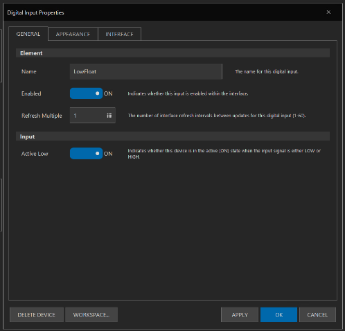
Here is a screen shot of the properties for one of the float switches. Maybe this NodeMCU just doesn't have the pull ups (are they on the silicon or on the board?)
upload_2019-7-12_16-21-35.png
 
Even with nothing connected, they have the state "ON", so the pin must be low. That seems backwards given the open circuit nature of those GPIOs.

I'm measuring it with a Fluke DMM, so that has an input impedance of 10M which shouldn't really effect the pin voltage assuming a pull up of 10s of K ohms.
 
Yeah, I'll just toss some resistors on it. It certainly isn't any obstacle to my application, but I thought I would mention it.
 
Nothing wrong with the FW. You need an external pull-up for each switch circuit.

I went back and RTFM'd and was surprised to see the claim to ensure pull-ups would be enabled. This blanket statement would presume that all supported input pins on all supported MCUs would be able to provide a pull-up.

Capture.PNG
 
Ouch! Yeah, we aren’t perfect! Our experience is based on general testing of the microcontrollers we support. When we port to other ones, admittedly we haven’t tested every model from every builder so we make some assumptions.

We’ll test this and circle back - im surprised to see this in the 8266, but we’ll confirm and remedy if can be.

That said, we appreciate you keeping us honest. Without the feedback we would blunder on with imperfections. It takes time to report issues - and we thank you for taking the time to note them.
 
I'm in the process of choosing an enclosure for my new BC system. Will either do a 20x20x8, 24x20x8, or a 24x24x8. I've got plenty of room in my brewery and I'm thinking one larger that the typical 16x16x8 would have room for growth and be easier to work in. Would appreciate some feedback here based on everyone's experience.

Also, a couple of questions. Many of the boxes that are priced somewhat "reasonably" have gland plates on the bottom which won't work for attaching the various connectors, but I was thinking that if I will need a large heat sink on the top, I could flip the box around and put the heat sink where the gland plate hole is?? Will I need a heat sink on the top of the box?

I'm looking for a knock-out punch kit to make the holes for the various connectors, but the kits only come with a few sizes and are quite expensive, except for a harbor freight one that has 1/2", 3/4", 1", and 1-1/4". Will probably wait till I have my parts to figure out what size holes I will have to punch. Any suggestions here?

This is a great thread and I appreciate everyone's help!
 
I have a 16x24x8 panel and I wouldn't want to go any smaller than that. I wouldn't consider my requirements to be particularly large and I only have a little extra space now. A lot of it gets eaten up in wiring channels and just spacing between parts. Empty space in your panel won't bother you at all while you brew but if your panel is too small it will be a pain forever.

I have my heat sinks inside the box and I have a fan that blows in cool air.

I used a few knock-outs that I had on hand, but most of my stuff I did with a step bit. That worked perfectly well and is pretty cheap. I don't know that I would invest in the knock-outs since you will likely have lots of different sizes you need that don't quite line up with the knock out sizes.

IMG_0585.JPG
 
I'm in the process of choosing an enclosure for my new BC system. Will either do a 20x20x8, 24x20x8, or a 24x24x8. I've got plenty of room in my brewery and I'm thinking one larger that the typical 16x16x8 would have room for growth and be easier to work in. Would appreciate some feedback here based on everyone's experience.

Also, a couple of questions. Many of the boxes that are priced somewhat "reasonably" have gland plates on the bottom which won't work for attaching the various connectors, but I was thinking that if I will need a large heat sink on the top, I could flip the box around and put the heat sink where the gland plate hole is?? Will I need a heat sink on the top of the box?

I'm looking for a knock-out punch kit to make the holes for the various connectors, but the kits only come with a few sizes and are quite expensive, except for a harbor freight one that has 1/2", 3/4", 1", and 1-1/4". Will probably wait till I have my parts to figure out what size holes I will have to punch. Any suggestions here?
This is a great thread and I appreciate everyone's help!

When I did a redesign of my BCS to Brucontol setup I considered what sort of automation I would be adding to my system, as well as any potential future upgrades. I decided to go with a 700mm x 500mm x 250mm panel thinking the additional space would be more than enough for future upgrades. At the time this panel looked huge compared to my BCS setup, but I can say with no regrets I made the right decision, since I eventually went with a combination brew/fermentation setup in one panel. Automation requires available space (input/output connections, analogue/thermistor-RTD boards etc..) and available space is key to any panel build, too little space and you are restricting your possibilities to what your end goal will be.
As far as the panel configuration itself I went with all my inputs/outputs on the side and large heatsink on top. The side mount outlets/inputs allowed additional space to mount equipment on the bottom plate of the panel as a result.
As far as knock out punches go, I went with used Ebay individual/sets. I have accumulated a dozen or so punches (Greenlee radio chassis type) for a fraction of the cost of new. The way I looked at it was I will be using these as a one time deal, not as a tool I will be using daily.
 
Last edited:
I agree with the above about case size - get the biggest one you can fit or afford.

Regarding the gland plate, I don’t see any reason you can’t put the HS there, as long as the SSRs will mount underneath. Technically, heatsinks are more efficient if mounted sideways rather than on top, so if that could be an option, don’t shy away.

Regarding the punches, it depends on material. If steel, I suggest cheap punches if using only a couple of times or step bits. Carbide hole saws for the bigger ones. If stainless, you’ll need higher quality stuff. Always should check if punch size will match your needs - they are trade sizes, not actual (e.g. a 1/2” punch isn’t a 1/2” diameter).
 
I agree 12V is a lot for the MEGA linear regulator to burn off. It’s just convenient as you are all mentioning since other hardware is 12V. I like the headroom the over-voltage provides for most, but admittedly run my personal rig on a 5V clean supply.

Some boards do a good job of sinking excess heat, others notsomuch. A self adhesive heat sink would never hurt!

Where would one place the heat sink? On the voltage regulator?
 
Ok thanks. That is what I was afraid of. The regulator on my mega blew yesterday after 6 months. It had been powered by a 12v psu. On to the next upgrade!
 
Last edited:
Just being cautious here. Ready to buy 25' (will need 20 - 25') of 6-3 wire. I'm assuming no reason for a metallic sheathing, so NM-B will be fine and the #6 will be fine for the max of 25'.

%236%20Wire.jpg
 
Just being cautious here. Ready to buy 25' (will need 20 - 25') of 6-3 wire. I'm assuming no reason for a metallic sheathing, so NM-B will be fine and the #6 will be fine for the max of 25'.

%236%20Wire.jpg
not sure where it is going but you may be able to get a 50A RV cord for cheap if you look around.. they are 6/3 (with 8/1 ground) SOOW
 
I can’t see the pic, but what run of wire are you describing? Through a ceiling or wall? Or to the rig?

You can use NM for the former but not the latter.

I am running the 6/3 from my outside box into my basement (where my rig is) along with all the other house wires. It will go through conduit thru the outside wall; actually thru the bottom sill. Are you saying that I need to use metallic sheathing since it powers the rig? What is the reason for using metallic sheating? Just want to make sure because NM is much cheaper. Thanks.
 
I’m not an expert on code so cant commit any facts... but my understanding is non-metallic cannot be exposed - it needs be behind a wall or in an attic, otherwise, in a conduit.

Thanks BrunDog. If that's true, I wonder if that is for all wire gauges/amperages or just for the big stuff. I have an old 1916 house that was originally knob and tube. When the electrician rewired it all the house wiring was brought in through the basement and it is exposed and twist tied into bundles. The large 50a wire for the a/c units of course is outside and in conduit. I'll check with an electrician. Only issue of using NM if metallic is required would be at inspection on resale.

Edit: Looks like from the site notes that the breaker will need to be a 50a gfci breaker which would make sense sense the rig is a wet area, but damn $10 regular breaker vs $98 gfci breaker
 
Last edited:
Thanks BrunDog. If that's true, I wonder if that is for all wire gauges/amperages or just for the big stuff. I have an old 1916 house that was originally knob and tube. When the electrician rewired it all the house wiring was brought in through the basement and it is exposed and twist tied into bundles. The large 50a wire for the a/c units of course is outside and in conduit. I'll check with an electrician. Only issue of using NM if metallic is required would be at inspection on resale.

Edit: Looks like from the site notes that the breaker will need to be a 50a gfci breaker which would make sense sense the rig is a wet area, but damn $10 regular breaker vs $98 gfci breaker

Yeah, I think if it is exposed it needs to enclosed. And "yup, I feel ya" on the sticker shock on 50amp GFCI breakers. :)
 
Back
Top