BruControl: Brewery control & automation software

Homebrew Talk - Beer, Wine, Mead, & Cider Brewing Discussion Forum

Help Support Homebrew Talk - Beer, Wine, Mead, & Cider Brewing Discussion Forum:

This site may earn a commission from merchant affiliate links, including eBay, Amazon, and others.
I also have 24VAC, 24VDC, 12VDC and 5VDC plus a 750 AC travel router and a RPI 3B+ in my cabinet ( I used valcro on one side of the cabinet for the router and RPI). I agree, tightvnc is a good way to go. I switched from teamviewer to use less resources. Don't use Microsoft RDP. There is an exploit out there that takes advantage of the port RDP uses to take over systems.
 
Yes you can connect an Ethernet switch in your basement to a long cable back to your router and plug both the mega and the laptop into it. That's what I am doing to connect all my devices in the garage back to my router in the house.

I use tightVNC instead of remote desktop or TeamViewer. It's free and allows for multiple simultaneous remote connects back to the same PC. This is convenient for me as I run brucontrol on a separate PC than my main desktop in the house. I also have a small fanless PC in the garage for my brew stand, so I can go between the house and garage and I can stay connected to the brucontrol server from both PCs.

Thanks crane. I'll check out tightVNC. Eventually I'll want to dedicate a pc to the brewery as I incorporate my fermenters and kegerator. Not sure how that will work if BC is installed on my desktop because I turn that off at night.
 
View attachment 633398 View attachment 633400 View attachment 633401

This is how mine is set up.

Pic #1 Micro USB (black) into RobotDyn MEGA which is mounted to a screw shield
Pic #2 Power Boost module with regular USB type "A" out to MEGA and micro USB in from 5.2VDC wall power supply. I'll move this to a DIN receptacle later.
Pic #3 Battery connected to Power Boost and switch using JST Connector.

To perform FW updates unplug regular USB type "A" from Power Boost module and into the laptop. Leave Micro USB connected to MEGA, it doesn't need to be moved.
I need to clean up the Power Boost (reroute) cables now that I'm done testing.
***If you decide to go this route you will have to decide which way to power your W5500. I ran a jumper on this board from the 3.3VDC pin to pin 7 as I was nervous about removing the solder pad jumper on the back, this allows the Ethernet W5500 to function.***
Parts list, please. I am not an Audrino guy so a lot of this is not plain to me.
 
@oakbarn


These are the parts I used but depending on your setup check the cable lengths for your application as well as the size of battery required for approximated backup time (mAh). Parts were ordered from https://www.adafruit.com/
I am assuming you have the RobotDyn MEGA/W5500 Ethernet and screw shield?

1 x PowerBoost 1000 Charger - Rechargeable 5V Lipo USB Boost @ 1A (1000C)
[ID:2465] = $19.95

1 x 5V 2.5A Switching Power Supply with 20AWG MicroUSB Cable[ID:1995] =
$7.50

1 x Fully Reversible Pink/Purple USB A to micro B Cable - 1m long[ID:4111] =
$3.95 ****Note*** this cable is cool because each end is totally reversible so you don't have to orient it to seat it in either the "Micro" or "A" sides. Unfortunately the better half got hold of it first so I settled for her old cell phone charge cable instead.

1 x JST 2-pin Extension Cable with On/Off Switch - JST PH2[ID:3064] = $2.95

1 x Lithium Ion Battery Pack - 3.7V 4400mAh[ID:354] = $19.95

Also be aware the Power Boost module is supplied with an "A" USB port press fitted into the module and you will have 5 solder points to lay down. It takes about 5 minutes and I'm not the best at soldering either.
 
Last edited:
I have decided to replace my 3 vessel, 2 pump, direct heat system (been brewing with it for several years) with an electric system automated with BC. This is a pretty long thread so I apologize upfront for asking questions that have probably already been answered. I really like @BrunDog's idea of a 2 vessel system, using the Quadzilla to accomplish the both the mash and the sparge, eliminating the need for the HLT. However, I still have to have a water source and I would like to eventually automate that. Right now I manually fill the MT and the HLT for my fly sparge and add salts. @BrunDog, I see in one of your videos that you have a couple of plastic RO water containers above your rig. I am assuming that you have an RO system that fills them; I don't see the hoses connected to anything so not sure whether you have filling your MT automated and without an HLT where is your sparge water coming from.

Anyway, I'm looking for ideas on how to incorporate water input into my design with the idea of automating at some point. Oh, I do have water (city, whole house treated) where my stand is. I use a potable hose to fill my vessels. Most of the time I use city water and sometimes use DI water (bottled at this time) depending on the treatment required.

Right now I am considering using an HLT but with no element assuming that the Quadzilla will heat the water to 170 for the mashout and sparge before it hits the MT.

Hi. Sorry for the very long delay in responding! A couple of trips including Homebrew Con has me distracted.

On my personal system, I fill the RO tanks via a separate RO system. They then feed the system by gravity - first filling to strike volume, then being used for sparge water.

I use a 5500 W element (the QuadZilla) to heat at both high power and low power (~1350 W). This is currently done via a Hi/Low relay that switches a hot leg and neutral, but I am pretty confident a 25% power limit could be done software alone. I use the high power to heat strike water, heat sparge water on the fly, and mashout. I use low power for mash temp control and mash steps.
 
I agree 12V is a lot for the MEGA linear regulator to burn off. It’s just convenient as you are all mentioning since other hardware is 12V. I like the headroom the over-voltage provides for most, but admittedly run my personal rig on a 5V clean supply.

Some boards do a good job of sinking excess heat, others notsomuch. A self adhesive heat sink would never hurt!
 
On my personal system, I fill the RO tanks via a separate RO system. They then feed the system by gravity - first filling to strike volume, then being used for sparge water.

I assume it would straight forward to automate filling the MT to strike volume using a volume level sensor.

How are you automating your fly sparge? Right now I fill my HLT with a calculated amount of sparge water. Fly sparging all of it and draining the MT fill my BK to the desired level. Are you automated the fly sparge until you reach the desired level in your BK? How do you know when to shut off your water source and finish draining the MT?
 
Yes, I use pressure sensors to measure volume.

Regarding the fly sparge... execution is a bit complicated via a script, but the concept is simple. Before sparging starts, the volume in the MT is measured as a start point. Then water is added at 1 qpm - this is handled by a proportional valve and flowmeter in a closed-loop fashion, opening or closing the proportional valve slightly to maintain 1 qpm. The drain to the BK occurs via another proportional valve, and it is controlled based upon the volume in the MT - if the MT gains volume above a certain window over the start point, the second valve opens slightly, and if the volume drops below the window below the start point, the second valve closes slightly . The water is heated by the RIMs tube to 170 degs F using duty cycle (usually around 65 percent depending on water ambient). If the temp drifts too far above or too far below, the duty cycle is bumped up or down.

The amount of sparge water is added per the recipe measured by the same flowmeter. When the limit is reached, the sparge stops and the system goes into "drain only" mode, filling the BK until the pre-boil volume is acheived per recipe. I do not have SG measurement in the system, so I have to manually keep an eye on the runnings to make sure they don't drop below 1.010. This is never a problem for beers above 1.040, only comes into play for smaller beers.

Hope that makes sense (maybe not as simple as I thought before writing those paragraphs). The script is essentially a loop that does measurements and adjustments every few seconds.
 
So you're feeding your sparge water directly from your RO container to your rims tube and it's able to heat to 170 before entering the MT? How does the grain affect your volume measurements? I suppose the initial MT reading is an arbitrary starting place and from there you're controlling the amount in and out. Once I get this down I don't really need the HLT unless I want to use the HLT like your're using your RO container. Thanks for helping me think thru this.
 
So you're feeding your sparge water directly from your RO container to your rims tube and it's able to heat to 170 before entering the MT? How does the grain affect your volume measurements? I suppose the initial MT reading is an arbitrary starting place and from there you're controlling the amount in and out. Once I get this down I don't really need the HLT unless I want to use the HLT like your're using your RO container. Thanks for helping me think thru this.

Yes, correct all the way around. The RIMs can heat to 170 on the fly at that slow sparge rate without issue. The MT reading is indeed arbitrary at that point - I just want it to stay about constant. I joke I don’t have an HLT but the water tank serves as a third “vessel”. You could feed directly from house water, but then it wouldn’t be RO.
 
Is it possible to reset an interface(MEGA) form within BC? Once in a while all my 1-wire sensors all go to -196.6 and pushing the button on the W5500 or power cycling the MEGA fixes it, but I am looking for a way to do it remotely.
 
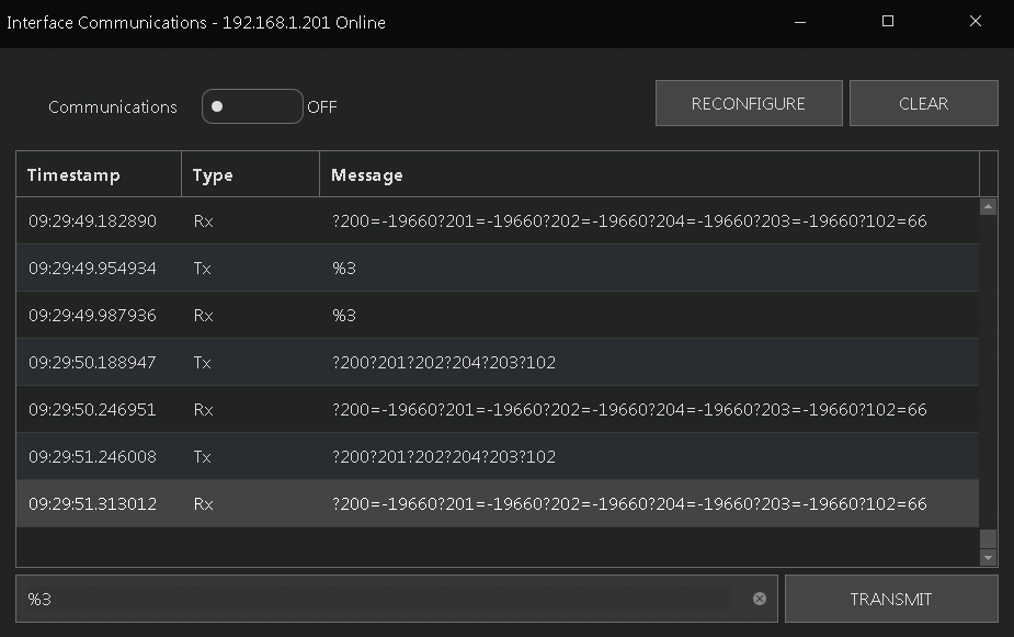
I have reinitialized the 1-wire from BC in the past, haven't had to do it recently... I believe you send %3 from the interface communications screen. I had to send it a few times then it popped back up.
 
tried %3 a bunch, communications window for that interface still shows -196.6 on all 4 sensors

upload_2019-7-3_17-48-20.png
 
Whew! Just finished reading all 2773 posts (okay, I skimmed a few dozen of them.) Hi there, new BruControl user. I'm rebuilding my home brewery after a few years away. I think I'll really like BruControl, and maybe I can contribute a few things from the process engineering world after a while.

First newbie question...I see the recommendation for a BruControl "server" as a machine with 8GB of memory. I've got quite a few retired 4GB machines around, including one Lenova touch screen laptop I'm eying for this purpose. But the memory on that machine is surface mounted, so I can't upgrade it. Is the 8GB recommendation based on anything other than it's stupid to have a Windows 10 machine with less?
 
tried %3 a bunch, communications window for that interface still shows -196.6 on all 4 sensors

View attachment 633866

Are you getting a %3 back? If so, this is likely a noise problem. Try debugging one sensor at a time. You can do this by unplugging all and trying one at a time (use %3 to re-initialize and you know every device post index 0 will not exist).

Depending on wiring you may need to shield the 1-wires.
 
Whew! Just finished reading all 2773 posts (okay, I skimmed a few dozen of them.) Hi there, new BruControl user. I'm rebuilding my home brewery after a few years away. I think I'll really like BruControl, and maybe I can contribute a few things from the process engineering world after a while.

First newbie question...I see the recommendation for a BruControl "server" as a machine with 8GB of memory. I've got quite a few retired 4GB machines around, including one Lenova touch screen laptop I'm eying for this purpose. But the memory on that machine is surface mounted, so I can't upgrade it. Is the 8GB recommendation based on anything other than it's stupid to have a Windows 10 machine with less?

Welcome! Not sure where that recommendation came from. BruControl does not take up a huge footprint. The 4 GB should be fine. You can always upgrade the computer if needed later.
 
Welcome! Not sure where that recommendation came from. BruControl does not take up a huge footprint. The 4 GB should be fine. You can always upgrade the computer if needed later.

Thanks!

And by the way, it came from BruControl-Manual-v1.1_5-17-2019.pdf, page 10: "Hardware: Any relatively modern PC, 8GB RAM, 100MB disk space available."

(For once in my life I RTFM! :D )
 
Whoops!

I guess we are saying “mo memory = mo betta”. 8GB is better but you should be able to get away with 4 so long as you don’t have a bunch of other stuff working. Try it and see if it works. The app does not require installation and is easy to move.
 
Memory functions have been trimmed quite a bit with firmware updates. I have a metric S ton of scripts and elements and workspaces. At most now it takes up a few hundred Meg. Where as it used to be a gig plus.
 
Thanks all! I suspected I'd be fine, but it's good to know it's not hard to move if it isn't. I'll give it a go and report back if I have any issues. I suspect I'm a really long way from the number of scripts that will push it.
 
Are you getting a %3 back? If so, this is likely a noise problem. Try debugging one sensor at a time. You can do this by unplugging all and trying one at a time (use %3 to re-initialize and you know every device post index 0 will not exist).

Depending on wiring you may need to shield the 1-wires.

Don't think I was getting anything back, don't remember, but this morning, I am(communications turned off to get screen shot):
upload_2019-7-4_9-31-1.png


Sensors are wired in a daisy chain with short branches to reduce noise, so cannot separate..

I tried slowing it to 10 seconds communications rate, no change.
This was the same problem I attributed to using the 12V power supply, but now on USB.. so maybe 12v was not problem..

Sensor 102 is analog and reporting fine, I know that pushing the reset button will fix it... Is there a command to reset the entire interface? That would really help! I may just wire an output to the reset pin as outlined in this link, but a 'reset' done in software as they describe, and placed on the interface page might be helpful too
 
Last edited:
Don't think I was getting anything back, don't remember, but this morning, I am(communications turned off to get screen shot):
View attachment 633984

Sensors are wired in a daisy chain with short branches to reduce noise, so cannot separate..

I tried slowing it to 10 seconds communications rate, no change.
This was the same problem I attributed to using the 12V power supply, but now on USB.. so maybe 12v was not problem..

Sensor 102 is analog and reporting fine, I know that pushing the reset button will fix it... Is there a command to reset the entire interface? That would really help! I may just wire an output to the reset pin as outlined in this link, but a 'reset' done in software as they describe, and placed on the interface page might be helpful too
I ran into a weird one-wire sensor issue a few years back where I had issues with multiple sensors on the same bus. In my case I could read each individual sensor fine on its own, but when I tried to read all 4 in rapid succession it would fail to read the last sensor with the highest address. Turned out the 5V was either too noisy or drooping after reading multiple sensors in a row. I had a one-wire breakout box inside the fridge that all of the sensors plugged into and was able to add a 10uF capacitor in the box to help hold up the 5V at the end of the main cable back to the rPI. Admittedly, I should have used larger gauge cable for the distance I was covering, but I was being lazy/cheap and trying to use up stuff I had lying around.

Probably not the same issue as you are experiencing, but thought I would throw it out there for food for thought while debugging your issue.
 
OK, wife and I came to the shop since it is near 7 breweries, and it is July 4th... I unplugged and re-plugged the sensor string with no change... a short reset button press had no effect, a 4-5 second reset button press made it work like nothing happened... not too many sensors, I had 8 on the string and it worked, I moved four to a ESP8286 SonOff, and they work 99.999% of the time... the MEGA ones work fine 99% of the time... once in a while they get hung...

I bought a slim Allen Bradley timer NO relay timer that will I will install to disconnect power to the MEGA for 10 seconds on a pulse from it on a GPIO pin.... I will write a script that shuts off multiple contactors if on, energizes the reset for a sec, waits 15 sec, and powers up the outputs that were on before the reboot in an orderly manner.
 
Last edited:
I have a question on ramp rate control. I looked in the manual and wasn't able to find anything that controls this directly.

What method is being used to control the rate of the ramp when going from one set point to the next? I looked at using the script to keep changing the target for the PID loop every N seconds. The other option is just figuring out what the output power is that I needed for the right ramp rate given the fluid volume and let it run open loop. The first one seems "ok", but the second one seems like it will have problems due to different rates of heat loss in the system and thus more output power required to do the higher temperature steps at the right rate. I guess I could do a lookup table and dynamically change it per step.

So I'm curious what others are doing to control ramp rates.
 
I use the PID element and max output setting. I have a 5500 watt element and I’m currently single or double vessel full volume. 25% for mashing. 50% for mash out. 100% for strike.
 
OK, wife and I came to the shop since it is near 7 breweries, and it is July 4th... I unplugged and re-plugged the sensor string with no change... a short reset button press had no effect, a 4-5 second reset button press made it work like nothing happened... not too many sensors, I had 8 on the string and it worked, I moved four to a ESP8286 SonOff, and they work 99.999% of the time... the MEGA ones work fine 99% of the time... once in a while they get hung...

I bought a slim Allen Bradley timer NO relay timer that will I will install to disconnect power to the MEGA for 10 seconds on a pulse from it on a GPIO pin.... I will write a script that shuts off multiple contactors if on, energizes the reset for a sec, waits 15 sec, and powers up the outputs that were on before the reboot in an orderly manner.

%3 resets the bus. If you are continually getting a -196.6 (-127 C) it means there is a communication error with one (or more) of the sensors. Powering on and off will likely not remedy the problem. Only addressing the hardware will.

I’m happy to help you debug the hardware. Pics, schematic, and/or a detailed description would help the most.
 
I have a question on ramp rate control. I looked in the manual and wasn't able to find anything that controls this directly.

What method is being used to control the rate of the ramp when going from one set point to the next? I looked at using the script to keep changing the target for the PID loop every N seconds. The other option is just figuring out what the output power is that I needed for the right ramp rate given the fluid volume and let it run open loop. The first one seems "ok", but the second one seems like it will have problems due to different rates of heat loss in the system and thus more output power required to do the higher temperature steps at the right rate. I guess I could do a lookup table and dynamically change it per step.

So I'm curious what others are doing to control ramp rates.

Can you share more info? Is this during mash heating? Some specifics might help guide a solution.

We have a plan to add ramping to duty cycle and analog/PWM outputs in an upcoming release, but you can easily do this in scripting right now.

Perhaps you are looking to drive a temp increase based on an existing temp? For example, drive a RIMs to exit its output at 3 degrees max above the current mash temp - this is also easily done in a script. I would not use PID... use duty cycle and set its output in your script loop.
 
I don't really have much detail at the moment. I just got my new kettles and so I'm starting to play with how exactly the system is going to work (now that I can try things for real). The setup is sort of a HERMS, but using a CFC to do the heating and the chilling supplied by water from a small third kettle. I control the heat in the third kettle similar to a regular HERMs, the only difference is that the strike water starts in the BK rather than the HLT.

The one thing that I don't have is a thermometer at the output of the CFC coil. I should probably get one, but at the moment I just have the temperature from the thermowells in the kettles.

I'll play around with the duty cycle in the script method. I guess without the temperature delta across the CFC I probably can't control much better than just doing max power output settings.

Thanks.
 
I'm integrating my Tilts into BC. Before this, I would monitor my fermentation progress remotely via Tilt > RPi zero > Google sheets. I'm wondering how to do this via BC in the new setup. I want to monitor the Tilts but also pressure transducers. Is there a way to have BC send data to a Google sheet? Or is there a different way to do this? I know the professional license can handle data exchange, but I'm looking for more hand holding to get me there. Appreciate the help!
 
Tilt only stores it locally in BC, but an industrious person could write a script to copy what the TiltPi does in the Windows environment that BC runs on. Because the Tilt is broadcasting a 'beacon', you could leave your existing setup for graphing and just use BC for control.

That being said, BC could use some improvement in the Tilt integration.
1 - let the interface (ESP32) read the beacon that comes every 2 seconds, not 10.
2 - let the user program how often or how many samples are used to determine the 'value' that will be charted. (450 of the 2-second samples is 15 minutes, pretty ideal for a fermentation graph)
3 - let the user program BC to 'throw out' values that are nonsense.. (if a value is outside the standard deviation, it is not counted in the average supplied for charting)
4 - let an interface (ESP32) run fermentation autonomously - that is, if the interface has the tilts and the digital outputs connected and hysteresis programmed, and BC gets disconnected, the interface can continue controlling the ferment.
 
Yup... I know my current setup will keep working, but I was hoping to get my pressure data as well. So looking for a way to get the data out of BC and access remotely
 
I think the easiest way will be using the Data Exchange Protocol outlined in the v1.1 manual and have a customized TiltPi installation to an HTTP GET from BC. More complex would be mimicking what TiltPi does, but on the BC Windows environment, in pushing data to Google.

Unfortunately, I do not think anyone has done this yet.
 
To be clear, I'm not married to the Google sheets approach. I'd there's another easier way to access the data remotely I'm open to alternatives
 
Some have had success with NodeRed as a “translator”. I would imagine this is relatively straightforward to set it up but admittedly haven’t done it myself. Others here have used it and perhaps can offer guidance.
 
NodeRed is what the TiltPi runs on, so it might be a pretty straightforward modification to the TiltPi flow to push/pull data from BC then to a Google sheet or other cloud provider.
 
Back
Top