BruControl: Brewery control & automation software

Homebrew Talk - Beer, Wine, Mead, & Cider Brewing Discussion Forum

Help Support Homebrew Talk - Beer, Wine, Mead, & Cider Brewing Discussion Forum:

This site may earn a commission from merchant affiliate links, including eBay, Amazon, and others.
How exactly have you looked?
Better to search "30a 2 pole contactor" The most common cheap heatink for ssrs found anywhere that sells ssrs are DIN mount they work great with a fan.. The best bang for the buck ssrs Ive found are the "Berme" branded MGR ssrs. These are the same ssrs auberins or ebrew sells too and you can get them there with a different label and better support if you need it but you will pay about 3 times as much with shipping. If you search amazon or ebay for 30amp contactors you will find many, I got mine from a seller called arlene and alice... A 25A din mounted 2 pole contactor was about $5 with shipping and I used 63amp ones for multiple elements (or anthing up to 63amps).. those are $10.
https://www.ebay.com/itm/CT1-2P-63A...470149?hash=item3ac503e5c5:g:-hwAAOSwT6pVn4E9

As far as smaller din mounted pcb board ssrs those are available from many seller on both ebay and amazon as well.

Thanks @augiedoggy. I’ve tried various searches but may have been using too much information. The price from arlene and alice is really good. I’ll probably order from them.
 
I can't seam to grasp how to write a script. How would I write something that makes relay 1 turn on when set temp on probe 1 is hit, like when my fermenter warms up and i want the pump to turn on. Also the same thing for relay 2 to turn on heater when probe 1 reaches certain temp.
 
First, I would say you probably don't need to write any scripts if you can use the native device elements. For example, in this case, you can set up two Hysteresis devices. Both read the same temp probe, but one is for cooling and the other for heating. Set the temp of the cooling device to be, say 65 degrees, with an ON Offset of 1, and it switches the relay which controls the pump. Then set the temp of the heating device to be, say 63 degrees, with an ON Offset of -1, and it switches the relay which controls the heater. Cooling will then come on when the temp is above 66 degrees and turn off when it goes below 65. Heating will then come on when the temp goes below 62 degrees and turn off when it goes above 63. That would leave a small deadband such that the heating and cooling don't alternate, cancelling each other out.

OR, if you wanted to write a script:
Code:
[fermenting_prep]
"Heat" State = off
"Cool" State = off
"Heat" Enabled = true
"Cool" Enabled = true
"Temp1" Enabled = true

[fermenting_loop]
if "Temp1" Value < 62
"Heat" State = on
else
if "Temp1" Value > 63
"Heat" State = off
endif
endif

if "Temp1" Value > 66
"Cool" State = on
else
if "Temp1" Value < 65
"Cool" State = off
endif
endif

sleep 5000
goto fermenting_loop

Just keep in mind this does not include any delays for compressors (you don't seem to have one), which need time in between turn-off and turn-on. You could add a 3 minute delay by adding "sleep 180000" after the "if "Temp1" > 66"" above.
 
Last edited:
The 2 Hysteresis devices is perfect for what I was looking to do. Is there any way to set it up for a fermentation profile like 62 for 3 days 67 for 2 days then 40 for several weeks?

Also when I tried to do the script way I get ERROR: Index was outside the bounds of the array. for the if "temp1" < 62 line. I've tried to change the values and still get the same results.
 
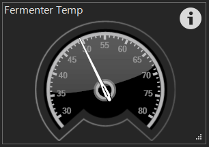
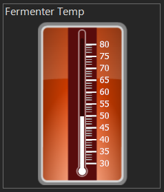
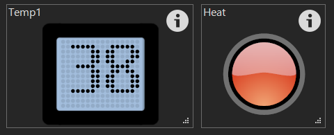
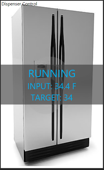
Happy Friday... Thought we would show a little teaser of some enhancements coming in v1.1! For device elements, you will be able to customize their appearance more...

LED style indicators:
LED1.PNG


Analog gauges:
LED2.PNG


Linear gauges:
LED3.PNG


LED Indicator and dot-matrix:
LED6.PNG


Change the ON and OFF text:
LED4.PNG


More teasers later!
 
Last edited:
You need to have an actual input device element with that EXACT name. Same with Digital Output device elements for Heat and Cool. I just created these names for the sake of the script example.


I used the exact name if it don't it wont let me get that far in the script, I'd get an ERROR: 'Enabled' is not a valid operator in the first line of fermenting_prep. When they are the same name I get ERROR: Index was outside the bounds of the array. in the first line of fermenting_loop

Those new temperature gauges look sweet
 
WHOA... Don't ever let the guy who designed the script system write scripts! My bad... the Value property was missing, so the line 'if "Temp1" < 62' should have been 'if "Temp1" Value < 62'. I fixed it above.
 
I thought it was something simple.

How would I set up a profile for fermentation. Like 63 for 3 days then 67 for 2 days and then 40 for several weeks
 
The Wemos, or any other supported interface micro-controller for that matter, receives an instruction from BC for each GPIO/port how to behave, and it does that in perpetuity so long as its powered. So in this case, it receives an instruction to read a temperature sensor from BC and then compare that temperature to a target, and if the temp is above/below the target plus/minus the offset, an output turns on or off accordingly. That output can drive a relay or whatever you have it connected to to cycle power (for cooling or heating or whatever). BruControl can continue to communicate with the interface and get temps, status etc., but if it loses communication, it will just keep performing that output control and stop reporting the temps, status, etc.

Make sense?
As long as it's powered? So if the controller is powered it's good, if it looses power and for some reason (network is down as an example) it's going to sit there and do nothing?

Just a small needle to request a future enhancement....

Amazing product, love the sonoff integration, we can watch our freezers now...

Thank you
Patrick
 
In the very rare situation that it loses power AND the communication to BC fails simultaneously, it will wake up and do nothing. If you are concerned this situation could actually happen, you can check for communication with a script and notify you via email or text immediately.

We can't fix power outages, but like I said, with battery backups, you are essentially assured to make it through an apocalypse!
 
Here is an example of a script which can run a fermentation schedule. This just adjusts temperature, but If you wanted to, you could spunding pressure also (with a pressure gauge and a blowoff valve, as @smort did above.)

Version 1.1 has date and time addressing in scripting, so this will need to change then, but will get simpler. It will also have Tilt reading, so you can automatically change the fermentation schedule based on the SG.

Code:
[start]
"Fermenter Temp" Enabled = true			// enables fermenter temp sensor device
"Fermenter Control" Enabled = true		// enables fermenter hysteresis device
new value daycounter				// creates a new variable named daycounter
reset "Refrigeration Timer"			// reset the timer (to its default of 0:00:00)
start "Refrigeration Timer"			// start the timer running
daycounter = 0					// set the variable daycounter to zero
"Fermenter Control" Target = 63			// set the starting fermentation temperature

[loop]
wait "Refrigeration Timer" Value >= 23:59:55		// wait for a day to elapse
reset "Refrigeration Timer"				// reset the timer (to default of 0:00:00)
daycounter += 1					// increase the variable daycounter by 1
if daycounter == 7				// if the 7th day, change the fermentation temp
	"Fermenter Control" Target = 65		// increase for diacetyl rest
endif
if daycounter == 8				// if the 8th day, change the fermentation temp
	"Fermenter Control" Target = 67		// increase for diacetyl rest
endif
if daycounter == 9				// if the 9th day, change the fermentation temp
	"Fermenter Control" Target = 69		// increase for diacetyl rest
endif
if daycounter == 14				// if the 14th day, change the fermentation temp
	"Fermenter Control" Target = 33		// decrease for cold crash
endif
goto loop					// go back to loop and wait again
 
Last edited:
BrunDog, after a lot of work and trial and error, I have been successful in running Windows XP with .NET 4 on the limbo emulator for Android. It will work on QEMU too. I used XP because I knew it ran BruControl, with the plan to get this running with XP (with a lower memory footprint) on a tablet after release. I need to be mobile, and don’t want to lug a laptop. Setting up Windows XP and BruControl on Android is a long process and takes a hell of a lot of patience, but is doable. It probably would work by setting everything up in a VM on a PC, but I had too many failures using VirtualBox with limbo, so I just let the tablet itself grind everything out which takes a day or so. The BruControl program itself takes about an hour to show on the screen and to be ready to go. Once it is running, my tablet (running Android 6 with two G memory and a 64 G high speed SD card where the “hard drive” is) connects to the Feather within the cabinet, and the two pumps and two propane burner indicators turn on and off with no latency, and the software alarm works too. So far, so good. Now, I want to run a script to see if it fully functions like a PC server. I don’t know how to write scripts, but I think I can read an existing script you had for an example well enough to get what I need. Please let me know what you think. I do have a water meter, which will be used with a Mega when I switch from the Feather. No motorized valves (yet). I can't send the script in this message. It is too many characters. I will see if it posts next.
 
[setup] // this section creates variables that I will use during the process. I put them here so I can easily find and edit the values

new value MashVol

new value SpargeVol

new value StrikeTemp

new value MashStep1Temp

new time MashStep1Time

new value MashStep2Temp

new time MashStep2Time

new value MashStep3Temp

new time MashStep3Time

new value MinFlowRate

new value MaxFlowRate

new string Status // this variable is updated along the way and displayed in a Variable Element on my brew Workspace (Can it be displayed on an LCD also?)

MashVol = 9 // here are the numbers put in the variables created above

SpargeVol = 10

StrikeTemp = 162

MashStep1Temp = 106 // mash temp is read at the Mash Tun Temp sensor later, which needs be a bit higher than the mash, so 106 equals a 104 mash temp initially

MashStep1Time = 00:20:00

MashStep2Temp = 142 // mash temp is read at the Mash Tun Temp sensor later, which needs be a bit higher than the mash, so 142 equals a 140 mash temp initially

MashStep2Time = 00:20:00

MashStep3Temp = 160

MashStep3Time = 01:00:00

MinFlowRate = 0.9 // these are used for my electronic autosparge

MaxFlowRate = 1.1

MaxFlowRate *= 355 // here the conversion from quarts/min is changed to pulses per sec, because the rate on the counters do not have calibration yet

MaxFlowRate /= 60 // this basically says to take the number in MaxFlowRate and divide it by 60

MinFlowRate *= 355

MinFlowRate /= 60

[prep]

Status = "Ready to Start"

"Step" Type = CountUp // Step is my step counter, and I reset it every major step in the brew process

restart "Step"

"HLT Temp" Enabled = true // here I enable/disable all the devices I am going to need initially

"Mash Temp" Enabled = true

"Mash Level" Enabled = true

"HLT Temp" Enabled = true

"MLT Temp" Enabled = true

"Flowmeter 1" Enabled = true

"Pump 1" Enabled = true

"Pump 2" Enabled = true

"Water Input" Enabled = true

"Boil Temp" Enabled = false

"Chill Temp" Enabled = true

"Panel Alarm" Enabled = true
Check out
"CONTINUE" State = false // here I set the on screen “CONTINUE” button to be off

wait "CONTINUE" State == true // and here I check for the button to be pressed. This allows me to make sure the brewer is officially ready.

[prep_fill]

Status = "Prep Fill"

restart "Step"

restart "Master"

"Pump 1" State = off

[fill]

Status = "Fill"

restart "Step"

"Pump 1" State = on // here I turn on my pump to start filling my MLT from my HLT

wait "Mash Level" Value >= MashVol // here I wait for the appropriate water level to be achieved in the MLT, set in the variable above

[prep_strike]

Status = "Prep Strike"

restart "Step"

"Pump 1" State = on // here I start recirculating

"HLT Temp” State = on // here I start heating

[strike]

Status = "Heat Strike"

restart "Step"

new value PreStrikeTemp // here I create and manipulate some variables for my strike water temp

PreStrikeTemp = StrikeTemp

PreStrikeTemp -= 3

wait "Mash Temp" Value > PreStrikeTemp // here I wait until the mash temp reaches 3 degrees below my strike temp

[strike_loop]

if "Mash Temp" Value >= StrikeTemp // here is a loop where the strike temp is looked for

"Brew Alarm" Active = true // when it is reached, the alarm is turned on to alert the brewer

"MashTemp" Target = StrikeTemp // now the burner temp is reduced to maintain strike temp

goto dough_in // and now go to the dough-in section

endif

sleep 3000

goto strike_loop

[dough_in]

Status = "Strike Ready"

restart "Step"

"CONTINUE" State = false // wait for the brewer to press the button

wait "CONTINUE" State == true

"Brew Alarm" Active = false // when he does, turn off the heat, turn off the alarm, turn off the pump to allow for dough-in

“HLT Heat" Enabled = false

"Pump 1" State = off

sleep 3000

"HLT Heat" State = off // set the HLT burner for mash maintenance

Status = "Dough In"

"CONTINUE" State = false

wait "CONTINUE" State == true // after dough-in, the brewer hits the button again

[mash_step1] // here is the first mash step

Status = "Mash Step 1"

restart "Step"

"Pump 1" State = on

sleep 3000

"HLT Heat" Target = MashStep1Temp // set the burner temp to the variable set in the beginning

"HLT Heat Target" Enabled = true

wait "Step" Value >= MashStep1Time // wait for this step to end its time

[mash_step2] // repeat for steps 2 and 3. I could have as many as I want, but three is more than I ever do

Status = "Mash Step 2"

restart "Step"

"HLT Heat Target"= MashStep2Temp

wait "Step" Value >= MashStep2Time

[mash_step3]

Status = "Mash Step 3"

restart "Step"

"HLT Heat Target = MashStep3Temp

wait "Step" Value >= MashStep3Time

[mashout]

Status = "Mashout"

restart "Step"

"HLT Heat" Enabled = false // now turn the PID off briefly

sleep 3000

"HLT Heat" State = on // turn on the high power again

sleep 3000

"HLT Heat" Target = 172

wait "Mash Temp" Value > 168 // wait for the mash to achieve mashout temp

[prep_sparge] // ok now we are going to batch sparge.

new value MashTopLevel

new value MashBotLevel

Status = "Prep Sparge"

restart "Step"

"HLT Heat" Enabled = false

sleep 3000

"Pump 1" State = off // turn off the pump and let the mash level be measured

sleep 3000

MashBotLevel = "Mash Level" Value // measure it and store it

MashTopLevel = MashBotLevel

MashTopLevel += 1 // create a variable for 1 quart higher

"Boil Temp" Enabled = true

"Flowmeter 1" Enabled = false // here I disable the flowmeter, and the re-enable it again to reset it

sleep 5000

"Flowmeter 1" Enabled = true

"Pump 1" State = on // turn on both pumps

"Pump 2" State = on

sleep 3000

"HLT Heat“ = on

[sparge]

Status = "Sparge"

restart "Step"

new value SpargeLoop

SpargeLoop = 0

[sparge_loop] // ok this will look complicated at first, but it is just a loop that gets run through every second

SpargeLoop += 1

if "Flowmeter 1" Value >= SpargeVol // check if the sparge volume was reached

goto drain

endif

if "Mash Level" Value > MashTopLevel // check if the sparge water caused the water level to rise up to a threshold

SpargeLoop += 2

endif

if SpargeLoop >= 5

endif

if "Mash Temp" Value > 175 // if the sparge temp is too high, turn off the HLT burner

"HLT Heat" = off

endif

if "Mash Temp" Value < 165 // and if the sparge temp is too low, fire up the HLT burner

"HLT Heat" = on

endif

SpargeLoop = 0

endif

sleep 1000

goto sparge_loop // here is the end of the loop. So basically this is self tuning the flow rate and the sparge temp.

[drain] // once the sparge volume is added, it is time to drain off the bottom

delete MashTopLevel

delete MashBotLevel

delete SpargeLoop

Status = "Drain Mash"

restart "Step"

"HLT Heat" Enabled = false

"Pump 1" State = off

sleep 5000

"CONTINUE" State = false

[boil]

Status = "Boil Ramp"

restart "Step"

"Pump 2" State = off

"Boil Heat" Enabled = true // now we heat the boil kettle at full power

"Mash Temp" Enabled = false

"Mash Level" Enabled = false

"Flowmeter 1" Enabled = false

"HLT Temp" Enabled = false

"Step" Type = CountDown // we change the step timer to a count-down type, so we can add hops/adjuncts per schedule

"Step" Value = 01:00:00

wait "Step" Value <= 00:05:00 // when 5 minutes are left in the boil, turn on the valves to let the wort run through the chiller circuit to sanitize it

"Chill Temp" Enabled = true

sleep 10000

"Pump 2" State = on

"Boil Heat" = on // turn on the Boil Heat again because the chiller circuit will kill the boil

wait "Step" Value <= 00:05:00 // boil done

"Boil Heat” Enabled = false

[chillboil] // here is a loop where the chiller is turned on for 30 seconds, the kettle temp is checked to be below 175, then start a whirlpool

Status = "Chill Boil Kettle"

"Chill Flush" Enabled = true

[chillboil_loop]

"Chill Flush" State = on

sleep 30000

"Chill Flush" State = off

sleep 15000

if "Boil Temp" Value <= 175

goto whirlpool

endif

goto chillboil_loop


[whirlpool] // whirlpool fast (no chillers), then slow (with chillers)

Status = "Whirlpool Fast"

"Step" Type = CountUp

restart "Step"

wait "Step" Value >= 00:10:00

Status = "Whirlpool Slow"

wait "Step" Value >= 00:15:00


[transfer_prep] // time to transfer to the fermenter

Status = "Transfer Ready"

restart "Step"

"Brew Alarm" Active = true // warn the brewer

"CONTINUE" State = false

wait "CONTINUE" State == true // wait for the button to be pressed to continue


[transfer] // do the transfer. Currently a manual valve is adjusted to control the chilled wort temp

Status = "Transferring"

"Brew Alarm" Active = false

"Boil Heat PID" Enabled = false

"Chill Flush" State = on

"CONTINUE" State = false

wait "CONTINUE" State == true // once done, the brewer hits the button again, and …

[shutdown] // everything shuts down, because the “Brew Shutdown” process is run which does it

start "Brew Shutdown"

stop "Brew" // kills this own process to make sure it doesn’t wait or run again
 
I should add that the script appears to need water level sensors which I also have but did not install until the feather is replaced with the Mega.
 
Other than the “takes and hour” part, it’s sounds interesting. In all candor, I do wonder if the effort is really worth it considering many people have some older machines/laptops that can be repurposed, or a mini-pc that is more than capable which can be had for under $150. In your case mobility is important, but I would assume a laptop could fit the bill for many.

That said, thanks for blazing the trail - its interesting to hear that BC can run on a different platform!
 
I like to think outside the box 'cause it's fun. Please help me with the script l posted for use with two pumps, two propane burners, and an lcd. Looking forward to v 1.1.
 
Yes - creating new stuff is indeed fun.

Regarding the script - I can see it’s based on the one from my rig I posted at some point back. The challenge with script help, especially one this long and comprehensive, is that the devices, types, etc. are unique to a rig - so without knowing those it would be very challenging to tell you what’s right and wrong.

I would suggest you test the script in sections to get each one right. If you have a problem with a particular line or section, post that here and we can help fix it.
 
Hi all,

Received a question about how to interface a 5V flow-meter into a 3.3V interface.

The answer is you would use a voltage divider circuit... which is a fancy term for two resistors in series. You would use this circuit for any 5V device output into a 3.3V input. You could also use off the shelf voltage dividers, but this is really simple.

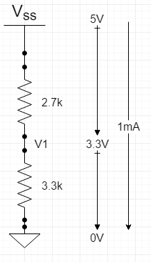
The interface impedances are very high, so we need hardly any current flowing into them. Let’s plan on 1mA (even though they wont need it). Using ohm’s law E=IR, rewritten as R = E/I, so at 5V/0.001A = 5000 or 5k ohm. Now, dividing 5V into 3.3V and the remainder, which is 2.7V would be done proportionately, therefore a 3.3k ohm and a 2.7k ohm resistor in series (added) would create the dividers. See graphic below.

So, putting these resistors in place, where Vss is the output of the flow-meter (5V output when high) and the other side is ground, you would wire from the midpoint of the resistors, marked V1 into the input of the interface. This way, when the flow-meter is in a low state of its square wave, the voltage will be zero at the interface, and when the flow-meter is in a high state of its square wave, the voltage will be 3.3V at the interface. Non-coincidentally, 3.3k and 2.7k resistors are common values, but if you don’t have either you can use other values or combinations to get close.

5V-3.3V divider.PNG
 
I like the idea of different text for an object depending on the state! Can you take it another step and specify a different picture depending on the state? Example of use is that you could have the picture of the pump impeller as greyish for not enabled, and then another picture with color in it when it is enabled? Obviously heating element would be an easy example as red when enabled, but you could do it with all of them.

I was also wondering if it is possible to have a graph that uses one of the calibration items for an object? Example would be the flow sensor. I added the calibration values that you have documented for the total flow so far, and the flow in liters per minute. I would like the graph to show the flow in liters per minute, but when adding the object in the graph value is the only option.

Finally I do have a question on scripting that I have not looked into yet. For the flow sensor, if the calibration data is set on the object, can that data be accessed while scripting, or do you need to redo the calibration setup within the script?
 
You will be able to change the background picture depending on the state in v1.1 - I didn't show that but its coming!

Sorry... I don't understand the graph question you are asking.

Let me check if the calibration values can be read or written. I think we left these out of the scripting because of the complexity but will double check.
 
For the graph question, I have the same flow sensor that you are using. I also have the calibration data that you have. I am not at my home computer, so I am going to try to describe from memory.

I have the calibration data that you posted somewhere to convert the pulses into liters, which makes the data continue to increase as long as there is a flow, so it is cumulative. There is also the calibration configuration that will show liters per minute. When looking at the object in the interface, it will show both values on the object. I want to add a graph that shows the liters per minute. However when I add the graph, or try to modify the graph, the only option is to show "value", no calibration data configuration is selectable for that object within the graph. So the graph is showing the cumulative liters value and there is no option that I can find to select the liters per minute data instead. When running the RIMS, cumulative liters value does not really help with visual clues that an issue might of happened, especially when not watching the screen constantly. This is why I was looking to have a graph, that would have at least 30 minutes of data shown.
 
Nice! The lag shouldn't matter in brewing as the pH changes very slowly. That said, you can reduce the lag by increasing the input Average Weight setting. Increase it as high as you need to, though at some point it may become a little jumpy around a value as some electrical noise is measured. Adding a small capacitor in parallel with the resistor may help reduce that noise also. Way to forge the path sir!
 
Any projected release timeframe for v1.1? Definitely looking forward to the I2C integration for my pH meter:)
 
We were targeting end of March, but you can see we didn’t make it (no April Fool’s joke). We are about halfway done with the list, so definitely before end of April.

As you can see, pH can be successfully integrated using the analog input. But I2C will give you another option too which will require a little less calibration work.
 
Hi all,

Received a question about how to interface a 5V flow-meter into a 3.3V interface.

The answer is you would use a voltage divider circuit... which is a fancy term for two resistors in series. You would use this circuit for any 5V device output into a 3.3V input. You could also use off the shelf voltage dividers, but this is really simple.

The interface impedances are very high, so we need hardly any current flowing into them. Let’s plan on 1mA (even though they wont need it). Using ohm’s law E=IR, rewritten as R = E/I, so at 5V/0.001A = 5000 or 5k ohm. Now, dividing 5V into 3.3V and the remainder, which is 2.7V would be done proportionately, therefore a 3.3k ohm and a 2.7k ohm resistor in series (added) would create the dividers. See graphic below.

So, putting these resistors in place, where Vss is the output of the flow-meter (5V output when high) and the other side is ground, you would wire from the midpoint of the resistors, marked V1 into the input of the interface. This way, when the flow-meter is in a low state of its square wave, the voltage will be zero at the interface, and when the flow-meter is in a high state of its square wave, the voltage will be 3.3V at the interface. Non-coincidentally, 3.3k and 2.7k resistors are common values, but if you don’t have either you can use other values or combinations to get close.

View attachment 563170


So Brundog, am I correct in thinking for a 0-1 volt input to a Wemos analog pin from a 0-5 volt pressure sensor would require R1=4k and R2=1k?
 
So Brundog, am I correct in thinking for a 0-1 volt input to a Wemos analog pin from a 0-5 volt pressure sensor would require R1=4k and R2=1k?

Using the analog pin is easier since Wemos D1 mini already has a onboard voltage divider to accept 3.3V to the A0 pin and reduce it to 0-1V to ADC. So to make A0 accept 0-5V you only have to add a 180K resistor between the sensor and A0 to make R1=180K + 220K=400K. R2 is onboard and is 100K. See the schematic of the board. Please note that this is only when using the analog pin, wiring a flowmeter to a digital pin will require a 5V to 3.3V voltage divider.
 
Thanks Brundog and smort, Further research after my post led me to that same conclusion and you have verified that now.

The pressure sensor has to be on the analog pin and not a digital correct?
 
Thanks Brundog and smort, Further research after my post led me to that same conclusion and you have verified that now.

The pressure sensor has to be on the analog pin and not a digital correct?

Yes correct, the pressure sensor has to be connected to the analog pin.
 
Thank you @smort! I definitely did not realize there is an onboard resistor!

I was never crazy about an A/D which only spans the 1V range... this makes it easier for sure.

Fortunately, the ESP32 has multiple analog inputs and are full range (3.3V).
 
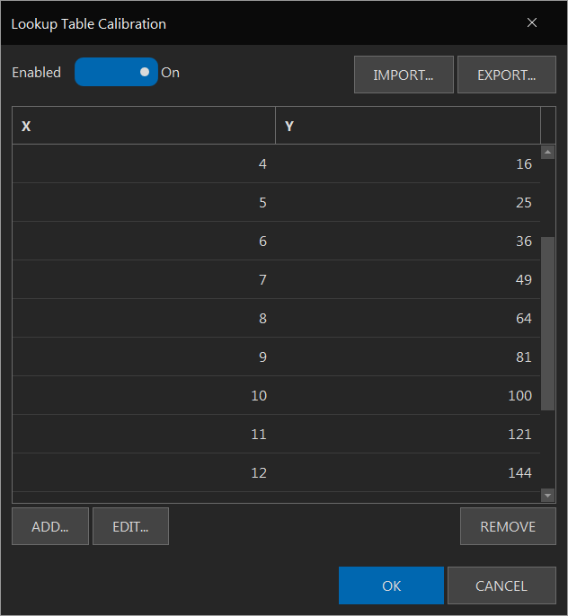
Since we are near the topic of calibration, I'll drop another teaser... We have added a lookup table calibration. This can be used to remedy non-linear analog to digital converters or create any curve desired (linear, polynomial, or non-parametric). You can manually add/edit points or even create a table externally (e.g. in Excel) and import it. Incoming data which does not match in input point will be interpolated across the neighboring output points.

Lookup.png
 
Back
Top