You are using an out of date browser. It may not display this or other websites correctly.
You should upgrade or use an alternative browser.
You should upgrade or use an alternative browser.
3-phase split load design
- Thread starter podz
- Start date

Help Support Homebrew Talk - Beer, Wine, Mead, & Cider Brewing Discussion Forum:
This site may earn a commission from merchant affiliate
links, including eBay, Amazon, and others.
The10mmKid
Well-Known Member
Excellent, just as I pictured in my head.
In my line of work, LINE almost without exception comes into the top of the breaker and LOAD exits the bottom.
Interesting that a ground fault will open the bad circuit and five of it's friends on that phase.
Podz, what condition exists when just one of the ground fault protectors trip on a 3-phase appliance? (I'm assuming the remaining two hold)
Thanks,
'da Kid
He hasn't shown you a picture of his box or even of the components in his box. For a magnetic/thermal breaker it doesn't matter which is input and which is output unless the panel in which the breaker is installed has wire lugs on one side and some sort of other terminals to mate with bus bars, for example, on the other.Excellent, just as I pictured in my head.
In my line of work, LINE almost without exception comes into the top of the breaker and LOAD exits the bottom.
I thought that was interesting too. Going to make for some interesting trouble shooting sessions.Interesting that a ground fault will open the bad circuit and five of it's friends on that phase.
He hasn't shown us connections for any three phase appliances. Just single phase branch circuits distributed across three phases. In all the stuff I've seen where a three phase load was protected by a GFCI/ELCB (or whatever you want to call it) the three phase conductors and the neutral all went through the doughnut in the breaker. Any current from any phase that did not return through one of the other phases or the neutral would trip the breaker disconnecting all three phases. Similarly, any magnetic or thermal overload on a single phase would trip the breaker and interrupt all 3.Podz, what condition exists when just one of the ground fault protectors trip on a 3-phase appliance? (I'm assuming the remaining two hold)
Does the main neutral bar get bonded to earth?
That diagram was just an example. I will try to get swmbo to help me take some photos today.
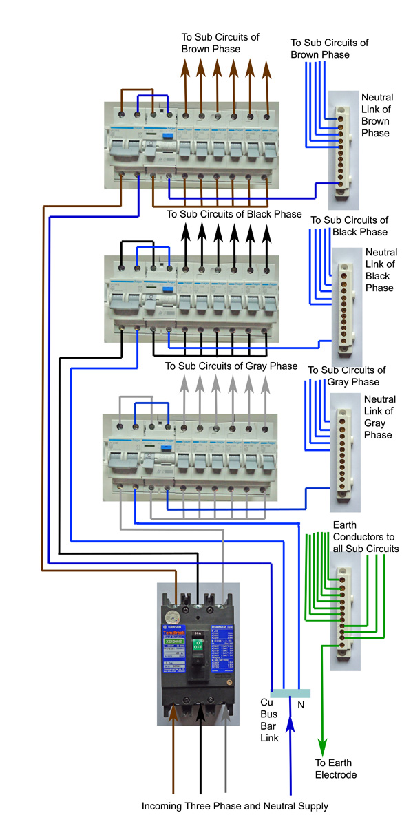
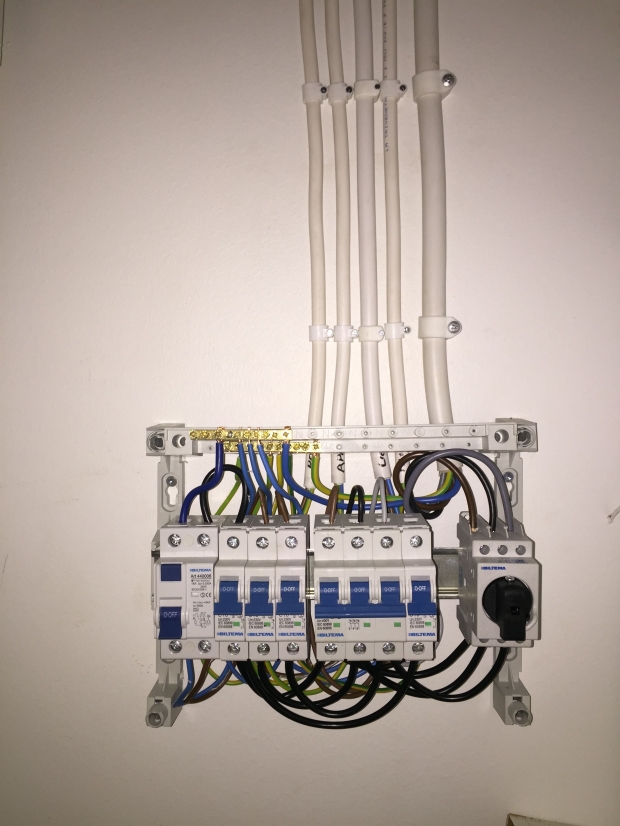
My design is different: I don't protect more than 1 circuit per residual current device, in order to avoid nuisance tripping. Also, I put the RCDs at the end of the row instead of the beginning so I can use bus bars to interconnect the breakers.
Similar to this:

I feed three-phase down to both of my sub panels with a single 20 amp breaker per phase in order to minimise outages, but my stove and brewing outlet are on 16 amp 3-pole simultaneous-trip breakers.

Stove doesn't require an RCD by code, but I do require one for my brewing outlet. I mounted it in a separate case since I didn't want to build a 3-row sub panel for the garage.

My design is different: I don't protect more than 1 circuit per residual current device, in order to avoid nuisance tripping. Also, I put the RCDs at the end of the row instead of the beginning so I can use bus bars to interconnect the breakers.
Similar to this:
I feed three-phase down to both of my sub panels with a single 20 amp breaker per phase in order to minimise outages, but my stove and brewing outlet are on 16 amp 3-pole simultaneous-trip breakers.
Stove doesn't require an RCD by code, but I do require one for my brewing outlet. I mounted it in a separate case since I didn't want to build a 3-row sub panel for the garage.
Does the main neutral bar get bonded to earth?
Yes, I have a TN-C system with PEN coming from the utility. And I'm only running one neutral bar anyway since I never protect more than a single circuit with a single RCD - just wire them straight together.
He hasn't shown you a picture of his box or even of the components in his box. For a magnetic/thermal breaker it doesn't matter which is input and which is output unless the panel in which the breaker is installed has wire lugs on one side and some sort of other terminals to mate with bus bars, for example, on the other.
DIN standard mini circuit breakers have places for wires as well as bus bars on both top and bottom so you have flexibility when wiring them up. Handy for the first circuit on a row, for example, where you can connect both a feed wire as well as a bus bar to feed the rest of the row faster.
We have three-phase bus bars as well. I use one in my kitchen sub panel because it's only a 1 row box. It looks like this:
Does the main neutral bar get bonded to earth?
As you are running separate neutral and protective conductors inside the building that would make it a TN-C-S. The grounding electrode puzzles me though. I'd be tempted to call that T(T/N)-C-S but there is, AFAIK, no such thing in IEC parlance. The NEC system is described as TN-C-S but also has the grounding electrode requirement at the service entrance.Yes, I have a TN-C system with PEN coming from the utility.
Anyway, it is most interesting to those of use completely parochialised by the NEC to get some exposure to how things are done in the rest of the world.
Yes, I have a TN-C system with PEN coming from the utility.
I see. Well, I was actually completely lost until I did a little reading.
As you are running separate neutral and protective conductors inside the building that would make it a TN-C-S. The grounding electrode puzzles me though. I'd be tempted to call that T(T/N)-C-S but there is, AFAIK, no such thing in IEC parlance. The NEC system is described as TN-C-S but also has the grounding electrode requirement at the service entrance.
Anyway, it is most interesting to those of use completely parochialised by the NEC to get some exposure to how things are done in the rest of the world.
I see your point. Although this terminoligy is new to me, I do not see a standard configuration that includes a grounding electrode. As an installer of many a ground rod, it seems ridiculous especially when much better grounding (earthing) options are available and actually requred to be used before driven rods.
I am enjoying the exposure to how things are done in the rest of the world. I have certainly learned a few things here and even if it is for curiosity's sake, it is valuable to me.
This old house doesn't have an equipotential bar, though I should install one and bury some copper in the yard. Connected to it should be the main breaker panel, rebar in the house, pipes, the metal roof, TV antenna, and ADSL connection.
Anyway, I've got neutral bonded to ground inside of the main panel and isolated inside the sub panels.
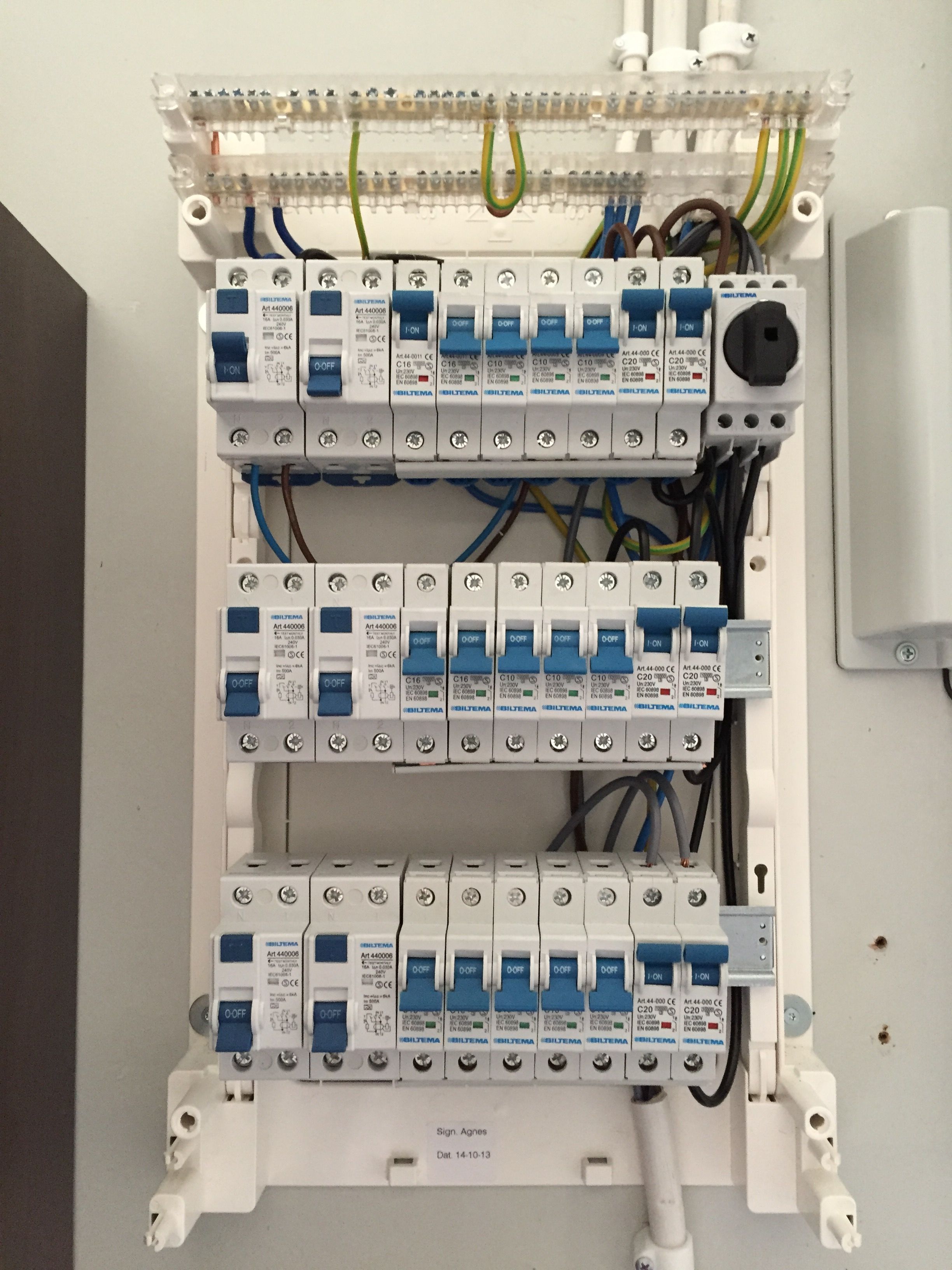
Still got four circuits waiting to migrate to the new panel. Those are a real pain because they trail through multiple rooms.
Anyway, I've got neutral bonded to ground inside of the main panel and isolated inside the sub panels.
Still got four circuits waiting to migrate to the new panel. Those are a real pain because they trail through multiple rooms.
This old house doesn't have an equipotential bar, though I should install one and bury some copper in the yard. Connected to it should be the main breaker panel, rebar in the house, pipes, the metal roof, TV antenna, and ADSL connection.
Anyway, I've got neutral bonded to ground inside of the main panel and isolated inside the sub panels.
Still got four circuits waiting to migrate to the new panel. Those are a real pain because they trail through multiple rooms.
So the way I understand, you will drive a rod (or use an existing electrode of some sort) and bond that to your supplied neutral in the main panel? Then the (equipment ground) is isolated in the subpanels...finally something that makes sense to me.
I would really like to see some pictures of your surface mount installation. That seems to be a last resort around these parts. Maybe you Europeans have a sexy way of doing it that we don't know about
There really is no need to do that unless you have special requirements of some sort (swimming pool, milking parlour...) and even in those cases the best approach is an equipotential surface around the pool etc. rather than lower impedance to earth. In the US the requirement is that the impedance be 25 Ω or less. A single rod is usually sufficient but if you have uncooperative soil a second one may be required.This old house doesn't have an equipotential bar, though I should install one and bury some copper in the yard.
If there is a problem with the PEN being above earth it is usually a problem with the utility and then often a poor connection in the neutral on the primary side. With the careful monitoring of phase imbalance you describe neutral current should be low. Does the utility run a Multiply Grounded Neutral? I would think they would given the northern latitude.
For example if my roof gets hit by lightning, it's currently ungrounded. It's a full metal roof.
Ground rods aren't allowed in the EU for new installations and I have never seen them here anyway. Minimum of 16mm2 cross section copper rope buried 80cm deep in a ring around the entire house, or 2x20m long sections if the ring is not physically possible. This is an EU-wide regulation.
Example:

Also look at pictures 3, 4, and 5 for allowed alternatives. Pictures 1 and 2 were the previous standard, so can be regularly encountered.
http://www.paneliankoskenvoima.fi/tuotteet-ja-palvelut-uusi-liittyma/maadoitus
Ground rods aren't allowed in the EU for new installations and I have never seen them here anyway. Minimum of 16mm2 cross section copper rope buried 80cm deep in a ring around the entire house, or 2x20m long sections if the ring is not physically possible. This is an EU-wide regulation.
Example:
Also look at pictures 3, 4, and 5 for allowed alternatives. Pictures 1 and 2 were the previous standard, so can be regularly encountered.
http://www.paneliankoskenvoima.fi/tuotteet-ja-palvelut-uusi-liittyma/maadoitus
Again, most interesting. In the US and Canada the realization that Fig. 2 is the safest is beginning to be accepted and is now required (in the US) around swimming pools. I have several times mentioned here that it would be the best for the electric, or any, for that matter, brewery and were I to redo my home setup would probably put a grid in the floor. A ground rod or rod or anything with < 25 Ω impedance is still required. That may seem high but I just checked my rod and it is 20 Ω but only injecting 13 mA into mother earth at the moment implying that the protective conductors in my house are 260 mV above ground. Clearly the system works.
Now if my earthing systems impedance were lower the voltage rise would be less. A loop buried 0.8 m deep would doubtless give a lower impedance here in VA but would it in Canada or Finland where I expect, at this time of year, that it would be imbedded in ice? Ground rods must be 2.5 m long in order to be sure that they reach below the frost line.
In the US and Canada most grounding problems, as I noted in an earlier post, seem to arise from problems with the primary neutral (corroded wire connectors) but that's because the utilities in those countries distribute the primary in a Y connection. This allows them to use lower voltage, single bushing transformers. It would be possible to protect consumers from neutral problems by installing devices which monitor the difference between earth and neutral voltage and isolate the PEN line to the consumer from the primary neutral if that rises. These cost money and the utilities generally dig in their heels when problems arise and blame inadequate grounding on users premises for the problem rather than install the devices. Given that 3ø is being distributed in Finland the utility has to be buying 3 bushing transformers anyway and so may be using a ∆ primary connection thus eliminating problems with primary neutrals by eliminating the neutral. The down side there is that more reliance must be placed on the customer's earthing. His only connections to Mother are at his premises and at the transformer. In the Y-connected MGN system he is connected to the neutrals at his premises, at his transformer, at every other transformer connected to the substation and every quarter mile in runs where there are no transformers.
80cm is the min depth, but of course impedance testing is required before taking into use. the primary intention of the circular loop is remote lightning strike protection, i.e current traveling across the ground, which happens during the time when the ground isn't frozen.
We also have a very shallow bedrock across most of the nordic regions... rock is exposed in many places, even in my yard. Driving a ground rod would require some heavy drilling and probably be pointless in the end.
finally got some photos inside my panel, will upload them later.
We also have a very shallow bedrock across most of the nordic regions... rock is exposed in many places, even in my yard. Driving a ground rod would require some heavy drilling and probably be pointless in the end.
finally got some photos inside my panel, will upload them later.
The problem you get into there is that a strike at one 'end' of the distributed ground injects HUGE current into the ground in its vicinity resulting in very large, very steep gradients. These induce very large currents in the grounding system some of which, on their way to the true earth potential at the transformer, may magnetically couple to the phases and damage electronic equipment. So that relates back to the question as to whether your utility uses a multiply grounded neutral (or a neutral at all). These are important in Canada (though they are used in the US as well) because of the large potential gradients induced by solar events. Even with MGN a CME in March 1989 wiped out Quebec's power grid. Shallow bedrock was cited as contributing to the problem. I'd guess it would be the same there.80cm is the min depth, but of course impedance testing is required before taking into use. the primary intention of the circular loop is remote lightning strike protection, i.e current traveling across the ground, which happens during the time when the ground isn't frozen.
What is the grounding system impedance requirement there?
We also have a very shallow bedrock across most of the nordic regions... rock is exposed in many places, even in my yard.
Same for my house in Quebec. I'm guessing that they built it onto the side of the hill rather than into the side of the hill but nevertheless it is earthed with a rod and the generator has another rod. Modern thinking is that that second rod shouldn't be there (because of the lightning strike problem mentioned above) and I've seen that one of the largest generator manufacturers in North America has removed installation of a rod from its installation instructions. I used to think the more wire you had in the dirt the better i.e. lower earth impedance had to be better than higher earth impedance but I am beginning to be swayed by the lightning argument.
Driving a ground rod would require some heavy drilling and probably be pointless in the end.
The obvious question then is that if you can't dig a hole below frost line for a rod how do you dig a trench below frost line for a cable?
Obviously, no one has yet come up with a completely foolproof method of grounding. Solve one problem and another pops up, it seems. This is why I tend to favor the grid under the floor approach. It doesn't matter if your grounding system goes to 10 kV above earth. You won't be standing on earth, you will be standing on the grid and all your equipment/wiring is at its potential. But I'm sure that system has some pitfalls too.
What is the grounding system impedance requirement there?
Sorry for being short, but the hand...
http://fi.wikipedia.org/wiki/Sähköa...otentiaalintasausjohtimen_jatkuvuuden_testaus
Mittauksen suojajohtimen hyväksyttävä mittausarvo on 0,13 ohmia.
So, between 0.1 and 3 ohms.
No problem. Just curious. Please don't worry about it any further.Sorry for being short, but the hand...
So, between 0.1 and 3 ohms.Mittauksen suojajohtimen hyväksyttävä mittausarvo on 0,13 ohmia.
That actually refers to the protective conductor (no, I don't know any Finnish - the only word I know in the whole Finno-Ugric system is 'Sor', the Hungarian word for beer). I meant the requirement for the impedance between the grounding rod terminal and the earth. I (probably obviously) got the translation for the quote above from Google Translate and looked over the rest of the page. The translation isn't great but I did see reference to testing with inductive type meters but no acceptable value.
ajdelange said:That actually refers to the protective conductor (no, I don't know any Finnish - the only word I know in the whole Finno-Ugric system is 'Sor', the Hungarian word for beer). I meant the requirement for the impedance between the grounding rod terminal and the earth. I (probably obviously) got the translation for the quote above from Google Translate and looked over the rest of the page. The translation isn't great but I did see reference to testing with inductive type meters but no acceptable value.
I don't know what the impedance should be, need to ask my electrician who does the testing.
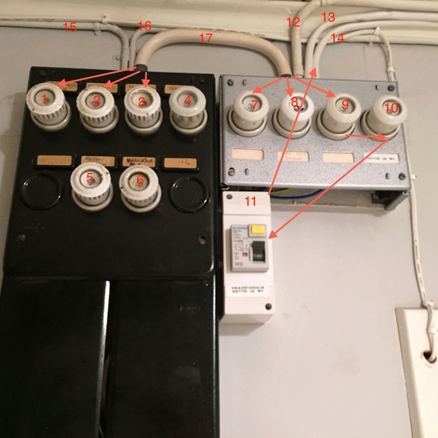
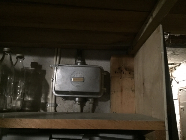
This was the beginning - prior to doing any work. Very old and dangerous setup.
1. 16 amp fuse feeding garage sub-panel (L1), also hotwired to 7 via cable 17
2. 16 amp fuse feeding garage sub-panel (L2), also hotwired to 8 via cable 17
3. 16 amp fuse feeding garage sub-panel (L3), also hotwired to 9 via cable 17
4. 10 amp fuse feeding entire ground floor (kitchen, living room and bedroom) via cable 16
5. 16 amp fuse feeding most of the basement
6. 10 amp fuse feeding two outside lights via cable 15
7. 16 amp fuse feeding stove L1 via cable 12
8. 16 amp fuse feeding stove L2 via cable 12
9. 16 amp fuse feeding stove L3 via cable 12, also wired to 10 to feed 11
10. 16 amp fuse feeding RCD 11
11. 40 amp RCD feeding a wall socket-lamp combo in the kitchen via cable 13 and the bathroom via cable 14
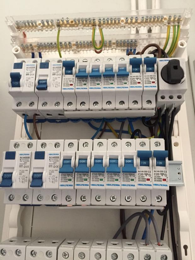
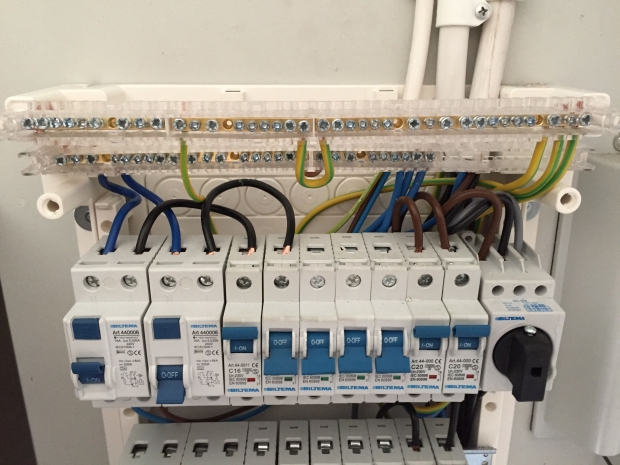
New sub panel in the kitchen. Lamp breaker on the far right isn't wired up in that photo. Three phases without bus bar, just wired the breakers together on the bottom side by hopping over. The second breaker on the right is a three-phase simultaneous trip breaker, feeds the stove. There is only one RCD here, for the general-purpose sockets.
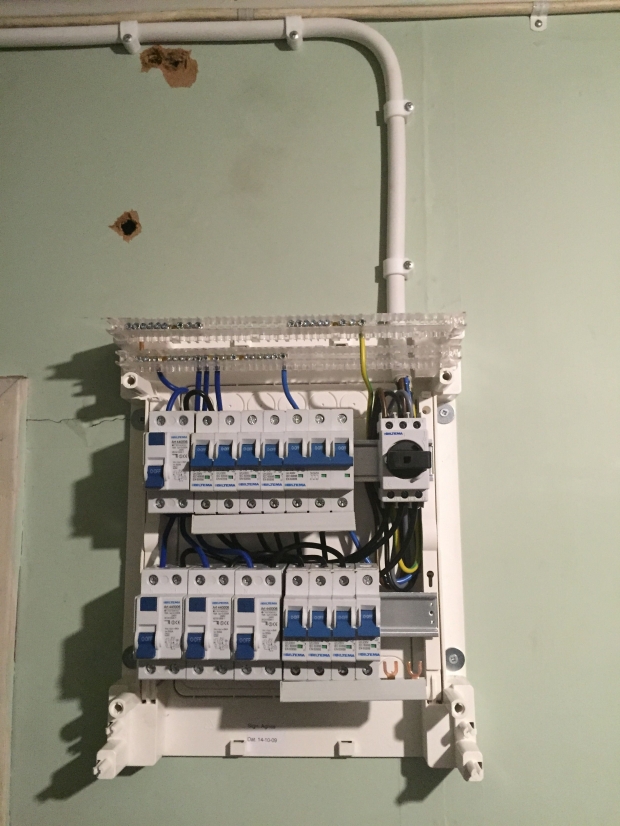
Yes, now I finally have a dedicated 16 amp 3-phase circuit and outlet in my garage with it's very own RCD (GFCI).
Now to start shopping for a 3-phase stainless steel water heating element. I'm guessing 8000 watts max for this circuit (line to line voltage of 400, power factor .8). How does that sound?
Now to start shopping for a 3-phase stainless steel water heating element. I'm guessing 8000 watts max for this circuit (line to line voltage of 400, power factor .8). How does that sound?
BazzookaBuddy
Member
- Joined
- Mar 15, 2014
- Messages
- 13
- Reaction score
- 1
Nice thread post. Quite interesting to read since I'm from Sweden and most of the threads here are related to American standards.
Let me know what element you purchase and your experience with it. I'm on the same route as you are.
Let me know what element you purchase and your experience with it. I'm on the same route as you are.
Nice thread post. Quite interesting to read since I'm from Sweden and most of the threads here are related to American standards.
Let me know what element you purchase and your experience with it. I'm on the same route as you are.
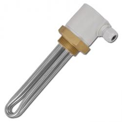
Here is an 8.5 kW 3-phase stainless steel element for 342 EUR including tax (damned expensive). I'd like to find something about half that price! But anyway, that should still run without tripping a 16 amp circuit.
http://www.esska-fi.com/esska_fi_s/...erre-2-messinki-korkki-505340200000-6540.html
The10mmKid
Well-Known Member
Might be worth checking one of our American suppliers:
https://www.watlow.com/downloads/en/catalogs/immersion.pdf
You'll have to 'up' your wattage since we're at 480V.
'da Kid
https://www.watlow.com/downloads/en/catalogs/immersion.pdf
You'll have to 'up' your wattage since we're at 480V.
'da Kid
Might be worth checking one of our American suppliers:
https://www.watlow.com/downloads/en/catalogs/immersion.pdf
You'll have to 'up' your wattage since we're at 480V.
'da Kid
You can not import electrical devices into the European Union unless they are CE marked. That is roughly the US equivalent of UL marking. They simply won't make it through customs.
http://ec.europa.eu/enterprise/policies/single-market-goods/cemarking/
In addition, every country has it's own organisation that needs to approve all electrical devices being imported or sold in that country. For example, in Germany it's called "TÜV" and in Finland it's called TUKES.
Now that I have a 3-phase outlet in the garage, I am able to connect one of these (a circuit box meant originally for construction sites):

It's got a 16 amp 3-phase input, then 2 x 16 amp 3-phase outputs and 4 x 16 amp 1-phase outputs (2 per circuit). 2 x 16 amp circuit breakers for the 1-phase sockets and a 40 amp RCD (GFCI) for the entire thing.
I can connect a 10 meter 3-phase extension cord to the outlet in the garage and then mount this thing to my brew rig and take it out in the yard! Or use a 3-phase welder, etc.
Do you have such devices in the US? This one only costs 67 EUR.
The10mmKid
Well-Known Member
Now that I have a 3-phase outlet in the garage, I am able to connect one of these (a circuit box meant originally for construction sites):
It's got a 16 amp 3-phase input, then 2 x 16 amp 3-phase outputs and 4 x 16 amp 1-phase outputs (2 per circuit). 2 x 16 amp circuit breakers for the 1-phase sockets and a 40 amp RCD (GFCI) for the entire thing.
I can connect a 10 meter 3-phase extension cord to the outlet in the garage and then mount this thing to my brew rig and take it out in the yard! Or use a 3-phase welder, etc.
Do you have such devices in the US? This one only costs 67 EUR.
OMG, heck no we don't have anything as gorgeous as that. Here is our closest sad equivalent.
The10mmKid
Well-Known Member
Still might be worth looking in to:
http://www.watlow.com/common/downloads_bak/en/agency/9999-0241-0000-L-Public.pdf
http://www.watlow.com/common/downloads_bak/en/agency/9999-0241-0000-L-Public.pdf
You can not import electrical devices into the European Union unless they are CE marked. That is roughly the US equivalent of UL marking. They simply won't make it through customs.
http://ec.europa.eu/enterprise/policies/single-market-goods/cemarking/
In addition, every country has it's own organisation that needs to approve all electrical devices being imported or sold in that country. For example, in Germany it's called "TÜV" and in Finland it's called TUKES.
OMG, heck no we don't have anything as gorgeous as that. Here is our closest sad equivalent.

That is really sad, indeed.
I don't think so, because homes are not wired 3ø in the US (people that want 3ø here have to make it from single phase). Nor do I remember seeing anything like that around shop floors or in labs or office buildings but that prove that they don't exist here.Do you have such devices in the US?
Curious as to why only two of the phases are supplied to single phase outlets. Are you fed corner delta?
Actually, I guess that's a pretty dumb question as previous posts make it pretty clear you are not.
I don't thing so, because homes are not wired 3ø in the US (people that want 3ø here have to make it from single phase). Nor do I remember seeing anything like that around shop floors or in labs or office buildings but that prove that they don't exist here.
Curious as to why only two of the phases are supplied to single phase outlets. Are you fed corner delta?
I think it just comes down to less of a risk of overloading the feeding 3-phase breakers. That, and symmetry. There are all sorts of different designs of these devices, this is a cheap one but it's IP44 and not supplied with it's own (restricted length) feeder cable, which I like.
- Joined
- Apr 11, 2013
- Messages
- 376
- Reaction score
- 61
What I am a bit jealous of is your 3ø power. I could do so much more at home if i had that.
A quick note. This is what I'm used to for quick power distribution on job sites in the US.

A quick note. This is what I'm used to for quick power distribution on job sites in the US.
What I am a bit jealous of is your 3ø power. I could do so much more at home if i had that.
A quick note. This is what I'm used to for quick power distribution on job sites in the US.
All houses here have it but most people don't use it for other than fixed-wire appliances like the stove, hot water heater, sauna heater, or underfloor heating.
Usually the only people who install a general purpose 3-phase socket are those who are welding or running some sort of workshop at home, which is like less than 1% of the population here.
What exactly would you do with 3-phase power if you had it at home?
The big advantages of 3ø are in motors and rectifiers. The former don't need starting/running capacitors and the latter have much lower inherent ripple. Most homeowners in the US who have 3ø equipment seem to be enthusiastic wood or metal workers who have obtained used factory planers, saws, lathes, milling machines... that have 3ø motors in them. Most of these guys make 3ø from the single phase coming into their houses by using a single-phased 3ø induction motor or simple capacitor based phase shifting circuits. There are lots of videos, etc., on the web that show how this is done.
Given the above I find it surprising that most of the 3ø loads in homes in Finland seem to be resistive. Are you saying that compressor motors in home heat pumps, for example, would be single phase?
Given the above I find it surprising that most of the 3ø loads in homes in Finland seem to be resistive. Are you saying that compressor motors in home heat pumps, for example, would be single phase?
- Joined
- Apr 11, 2013
- Messages
- 376
- Reaction score
- 61
Thanks for asking, as you seem pretty well versed in the world of electricity. Even from simple everyday things like a washing machine. Three phase power can increase your own electrical efficiency pretty tremendously.
From a common point between the two of us. Brewing. Meeting the power demands of a electric brewing rig can be quite daunting for brewers in the US. Many of the designs I see on HBT take into account the limitations of a bi-phase service and thus we are stuck with limited wattage.
Not to say that you don't have your own limitations with what you have.
I would certainly be interested in having the ability to use 3 phase motors, welders, and such things for a shop setup though.
I pulled this little blerb from another site which supports my jealousy. Mainly from an efficiency point of view.
I remember asking an engineering professor that same question. I.E. If a three phase motor is more efficient than single phase, how huch more efficient is it? He said without hesitation, "20 percent". I don't know if that is true, and that was in 1980, so things may have changed somewhat since then. However, you still can't get something for nothing. Compare full load amps on each machine. That's where the HP calculation comes from, so they can't be too far away from each other. One way of looking at the whole question would be to approach it form the "green" point of view and consider how much copper and iron are going to produce the same effect. As Tony says, "Looks can be deceiving". Generally, the 1 ph motor will have twice as much copper and iron as the 3 ph motor. That extra stuff is devoted exclusively to starting the 1 ph motor. When it gets up to normal operating speed, the centrifugal switch takes it out of the circuit. And as said earlier, the 3 ph motor runs cooler. I would attribute some of that to the start function in the 1 ph motor. WWQ
Are you saying that compressor motors in home heat pumps, for example, would be single phase?
For geothermal heat pumps, the motor is either to be wired as 3-phase or 1-phase connected via a safety switch. A safety switch is a switch that shuts off power if it notices the wire heating up i.e. the motor is not spinning for some reason.
The motor that circulates hot water in my house for heating and showers is wired with a safety switch. And it's a real ***** because every time I shut off power to the house, that motor refuses to restart on it's own. I need to unmount it, stand it on a shelf and hit the fins with my finger to kick start them. Then I need to let it run like that for about 15 minutes before it will restart on it's own with the safety switch before I can remount it.
Not to say that you don't have your own limitations with what you have.
Yes, well for example in Finland you can't get more than 3 x 63 amp service to a residence. That flatly eliminates any possibility of a 64 amp 3-phase residential power outlet. So, in practice, residential 3-phase is limited to a 32 amp outlet. Mine is limited to 16 amp because my service is 3 x 25 amp (3-phase outlets that you can buy for home use are either 16 or 32 amps).
Of course I have 6 x 20 amp breakers in my main panel that I feed down to 3-pole 16 amp breakers in my sub panels.
Not sure if the calculation is correct, but with 400v, 3-phase, power factor 0.8, an 8500 watt element should pull about 15.5 amps. So, that will clearly fit within my 16 amp circuit. I don't know if that power factor is correct or not, I just guessed it.
Assuming I heat 25 litres of water from 20c to 100c with an 8500 watt element, it should take 16.5 minutes. Not bad.
http://processheatingservices.com/water-heating-time-calculator/
Similar threads
- Replies
- 5
- Views
- 2K
- Replies
- 15
- Views
- 923
- Replies
- 0
- Views
- 715
