240V panel on 12/2 240V outlet

Homebrew Talk - Beer, Wine, Mead, & Cider Brewing Discussion Forum

Help Support Homebrew Talk - Beer, Wine, Mead, & Cider Brewing Discussion Forum:

This site may earn a commission from merchant affiliate links, including eBay, Amazon, and others.

Outbred

Well-Known Member
Joined
Apr 2, 2008
Messages
51
Reaction score
0
So I have a 20A, 240V outlet I use for my dust collector that is wired with 12/2 romex. There are 2 insulated wires which I assume are the hots (line 1, line 2) and a bare copper wire which I think is the ground or neutral or both (quantum style!).

Does it matter whether the bare wire is ground or neutral for the 240V only panel I've laid out below?

240-pid-2-64578.png


I'm basically trying to build this panel (http://www.instructables.com/id/Electric-brewing-system/?ALLSTEPS) but with a contactor in line so I can completely cut power and have a visual indication of when it is capable of being energized.

Thanks in advance. I know portions of this topic have been beaten to death.

Oh yeah, and Merry Christmas!
 
Your black line 1 and red line 2 are both carring 120v each, there both hot. It looks like you'r trying to use one here as a neutral, but you are sending 240v to the PID power, the switch, and the contactor coil.

Check out these diagrams: https://www.homebrewtalk.com/f170/list-pj-electrical-diagrams-382286/

Further reading: http://ths.gardenweb.com/forums/load/wiring/msg0711160913459.html

(edit)
Sorry, the data sheet for the pid you posted shows it's good up to 260v, the 110vac on the drawing threw me off.
http://auberins.com/images/Manual/Manual version 3.4.pdf
 
Thanks for reply.

The fact that all those diagrams have a separate ground and neutral is kind of confusing to me in this situation.

Would I use the single ground as both neutral and ground in my case?
 
No. Ground and neutral aren't the same thing, you wouldn't use it as a neutral. You've drawn it as ground which is correct, you want to make sure any metal enclosures are all properly grounded.

From the reading material I linked: "The current flows from the hot to the neutral in a typical 120v circuit. In a 240v circuit there is NO neutral, the current flows from hot to hot."

The pj drawings are using 1 hot and 1 neutral to create 120 v circuits except at the elements. Yours is all 240v.

I won't tell you whether your circuit is proper, I'll leave that to the many more knowledgable folk around here. I'll just say make sure your switch, contactor, and pilot light are all rated for 240v.
 
Gotcha.

Just read that big garden web post. Near blasphemy to use ground as neutral it seems.

As I recall all components are either explicitly 240v or 120/240.

Thanks again!
 
A couple things here....some you have figured out already.

1. Your PID controller requires a neutral which is not supplied by the 12/2.

2. You show a 4500w element. This will require a 30 amp circuit at 240v, fed with all #10 wiring. Read the element nameplate, but it should draw around 18.75 amps. You do not want to load your 20a circuit over 80% (16 amps). Especially when it feeds a process as critical as wort boil! ;)

3. I see two options :
A. Pull a new 10/3 (2 hot, 1 neutral, 1 ground) circuit from your panel and feed it with a 30a breaker. This will provide what you need for your control setup as drawn.
B. Get a lower wattage element, which will allow you to use the 12/2 for the element only. Then get a 120v circuit either from the house panel or a nearby outlet. The 120v circuit will supply the controls only.

I'll try to draw a diagram to show you exactly what I mean by seperating the two circuits.

BTW you do not need the second contactor ahead of the element. The SSR shows an output contact rated up to 480v @40 amps. You could just get one with 2 sets of contacts to feed both legs of the element.

And now for something that many won't want to hear but it should be said.

Most States - at least mine (Idaho) have adopted the NEC which governs electrical installations. A homeowner here can perform his own work but it still must be inspected in most cases. While the DIY bug is contagious- there is a very real threat to you, your home and family when performing electrical work without a license or fundamental knowledge.

Along with that, you are building a control panel that is not tested and approved by the UL laboratories. This is a newer code law that has been around for 8 years or so. This could cause big problems with your insurance company if say a catastrophic failure happened.

IMO you should hire a local electrician to perform any work that requires pulling circuits from your panel, and buy an approved controller from one of the vendors on this site.

Either way, I hope the beer comes out great!:D
 
Thanks for the reply.

Out of curiosity who are the approved controller vendors? Eg are any of the panels I see for sale UL approved?

I assume the blichmann one is but 600$ for a PID controller in a fancy case seems exorbitant.

Truth be told I was thinking about getting a RIMS rocket from them because I want the hop rocket anyway.

Are there any reasonably priced single element controllers that are UL tested?

I am relatively new to the site and would have to do some research before I could answer on the element, but as for Blichmann - their products apear to be high quality and highly accepted, so your gonna pay for that.....

You could call some of your local electrical control supply houses (I.E. not Home Depot) and they may be able to help you out. There are electrical contractors that have licensed some of their employees/engineers to be able to obtain UL approval for their control panels built in-house. Check out any contractor that wires up wells, pump houses, industrial controls, etc.

Out of curiosity, what is the purpose of the switch labeled element enabled? Was this so you could bypass the PID controller to turn on the element manually I assume?
 
That switch was intended to flip the contactor on and off. Without the contactor the second hot line would be connected directly to the outlet and there would always be one live line connected to the outlet when it was plugged in. It's also provides another bit of safety when using the panel in that I would need to plug it in, set the pid and hit the button before any current would reach the element.

At least that is my understanding of contactor use in these panels.

I got the idea for the wiring from the linked instructable in the original post. Seems like multiple people have made that panel without a neutral (eg hhg) but I wanted to verify that design here because I don't trust one random guy on the internet.

Thanks again.
 
I get the impression around here that the 80% rule really only applies to sustained loads over 3 hours. I'd personally be more comfortable with a bit more head room.

The specs for that pid say it will run off of 240, it still requires a neutral?
 
The Auber SYL-2352 doesn't need a neutral for a pure 240v set up. You have it powered correctly according to the manual.

Edit: Woops, thekraken has beaten me to it and has also posted the manual earlier in the thread.
 
I get the impression around here that the 80% rule really only applies to sustained loads over 3 hours. I'd personally be more comfortable with a bit more head room.

The specs for that pid say it will run off of 240, it still requires a neutral?

I see what you mean...I took the 85-260v listing as a nominal voltage rating of the contacts. However, the wiring diagram 5.4 does show the controller supplied with 240v single phase(120v each phase).

I personally would still want this size element on a 30 circuit....
 
OK I've made a few modifications to the diagram, specifically how the switch was wired and adding a breaker between the PID and the power.

Does anyone know if this is the proper way to wire these switches to control the contactor? I've looked at the wiring diagrams for both the contactor and switch but they seem to be wired differently in each of the examples.

1. SW1 swtich: http://www.auberins.com/index.php?main_page=product_info&cPath=7_32&products_id=223

2. 240V coil 30A contactor: http://www.auberins.com/index.php?main_page=product_info&cPath=2_31&products_id=403

3. 240V indicator LED: http://www.auberins.com/index.php?main_page=product_info&cPath=7_33&products_id=248

Thanks in advance.

240-pid-2-64581.png
 
It looks like you can get rid of the left most wire on your line 1 bus, it doesn't look necessary to me. Then your switch would be wired up just like it's first example diagram.
 
I think you're right.

The indicator light would still be in parallel without that wire.
 
For gfci's what kind of stats am I looking for for devices meant to protect people rather than equipment?
 
So I have a 20A, 240V outlet I use for my dust collector that is wired with 12/2 romex. There are 2 insulated wires which I assume are the hots (line 1, line 2) and a bare copper wire which I think is the ground or neutral or both (quantum style!).

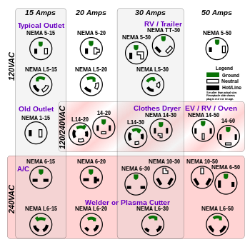
Your picture shows a NEMA 5-15/20 receptacle. That's a 120v receptacle. If you have hot-hot-ground, it should be a 6-20 receptacle.

350px-NEMA_simplified_pins.svg.png


Many 240v GFCI's need the neutral, see here.
 
Just going on what the outlet face looks like. I'm assuming (maybe erroneously) that the electrician used the correct outlet. Is there anyway to tell whether the guy wired it hhg rather than hhn?

Looking to get a gfci like this http://www.gfcistore.com/30-amp-inline-gfcis.html.

Thanks for the input

Get a multimeter! If you don't have access to one, buy one immediately! You can get them on Amazon for $15. You will easily be able to verify your outlet.

If you arent comfortable sticking probes in to check, abandon the project now. I'm all for learning as you enter new projects, but there isn't a lot of room for error with electricity. I'm not saying you shouldn't embark on this journey, I have learned a ton in the past few months myself, but you definitely shouldn't until you have some basic knowledge and confidence.
 
Multimeter is on my list.

I've done a lot of work with 120v around the house just trying to get familiar with 240v.

I've loved learning about the components of these panels.

If I'm uncomfortable at all I fully intend to stop until I've got it figured out. In no rush to get this project done. Want to make sure I fully understand before I embark.

Would a multimeter be able to tell a ground from a neutral with no load on the system? This is a dedicated circuit with only one outlet.
 
Ground and neutral act the same when tested with a multimeter, it provides a path to ground. Trace the circuit to your main panel and see if the third wire lands on the neutral buss or the ground buss bar. Never rely on what is at the outlet to make those assumptions. I see all kinds of mistakes done by someone taking shortcuts or lack of knowledge. Confirm it is a 240v circuit as well.
 
Would a multimeter be able to tell a ground from a neutral with no load on the system? This is a dedicated circuit with only one outlet.

Both are connected to the same point in the panel (or, more precisely, to points in the panel that are electrically bonded) so no, there is no measurement you can make that will tell you which it is. Electrically, there is no difference between a neutral and ground in a dedicated 220V 3 wire circuit. The fact that the wire you have is uninsulated suggests that it is wired to the earth bus and is, thus, a ground wire which is also suggested by the fact that the equipment connected was not a range or clothes dryer which were, at one time, exceptions in which the third wire was neutral.

Which it is doesn't matter as you have no asymmetric (120V) loads. Electrically speaking, that it. If it is connected to the neutral bus it is the wrong color and that might even be brought into compliance by putting some white tape around it at both ends but the fact that it is not insulated is probably still a problem. Easy enough to move it to the earth bar though.
 
Looks like you're closing in on the correct wiring.
Make sure every lamp, relay coil, the PID and switches are rated 240V

You can use those GFCI pigtails you linked to. The green wire will go to ground.
240V GFCI's do not require a neutral.

'da Kid

NEVER EVER USE A BARE COPPER WIRE AS A CURRENT CARRYING CONDUCTOR, I.E. as a neutral.
 
Your picture shows a NEMA 5-15/20 receptacle. That's a 120v receptacle. If you have hot-hot-ground, it should be a 6-20 receptacle.

Just going on what the outlet face looks like. I'm assuming (maybe erroneously) that the electrician used the correct outlet. Is there anyway to tell whether the guy wired it hhg rather than hhn?

This made me suspect it was not a 240v circuit, which is why I suggested verifying it in the previous post.
 
240V GFCI's do not require a neutral.
Actually, many of the modern ones do as their functioning, including ground to neutral fault detection, requires the presence of the neutral in order to be able to detect a fault to it and more importantly as the source for the power that runs the electronics. If you have only the ground present you can connect the neutral terminal on the GFCI to it. This is technically a code violation as you are using the ground as a current carrying conductor (though the current is only the couple of ma needed to run the GFCI's electronics.

This problem goes away if you have the older style GFCI which does not have the internal electronics (nor detect ground/neutral faults).

Or, easier still, replace the breaker in the panel with a GFCI breaker. The neutral is available there and there is really no reason to have the panel breaker and a GFCI in series. You could move the thermal/magnetic breaker to the outboard box, though, if you still wanted the disconnect.

NEVER EVER USE A BARE COPPER WIRE AS A CURRENT CARRYING CONDUCTOR, I.E. as a neutral.

The caveat here is that you shouldn't use the grounding wire as a current carrying conductor as that can allow the frame of connected equipment to rise above ground potential which clearly constitutes a hazard in the case of large non symmetric loads. It isn't the fact that the wire is uninsulated that constitutes the hazard (as it is, in Romex, of course insulated) but the fact that it is connected to equipment frames, which are not insulated.

This rule was, as noted in an earlier post, violated with the blessing of the code in earlier days in ranges and clothes driers where the grounding wire was the neutral wire on the basis that the asymmetric loads were small (pilot lights, timers).
 
Is there anyway to tell whether the guy wired it hhg rather than hhn?

Just look in the panel. As I said in an earlier post if he wired the bare wire to the neutral bar (HHN - unlikely) you can just move it to the ground bar (HHG). Electrically it doesn't make any difference* but you will now be code compliant.

If you are at all uncomfortable taking the cover off your panel don't do it! Be sure to open (turn off) the main (large at the top) breaker before doing this.

*An exception to this would be the case where the outlet in question is wired to a sub panel or where the service disconnecting means is not in the panel. In those cases ground and neutral are not bonded at the panel (but rather at the service entrance).
 
Great suggestions, thank you!

Suppose that is a 5-20 outlet wired 240v, does it need to be switched to a 6-20 to be up to code?

I might as well correct it now if so.
 
If you need to ask how to design electrical circuits then stick to ranges of current that are non-lethal. That's my advice.
 
Great suggestions, thank you!

Suppose that is a 5-20 outlet wired 240v, does it need to be switched to a 6-20 to be up to code?

I might as well correct it now if so.

First of all....YES!!!

Let's find out what you have first. If it was installed by an electrician and is 240v, that is a something that would not have passed inspection, as that is a serious error.

I am suspect of the entire circuit to be honest. Have a licenced electrician look at it before you go any further. Call up someone and ask for an onsite visit for a quote for a 240v circuit upgrade. They will jump at the opportunity. I suspect there is a chance this was not done by a professional.
 
I traced it back to the panel. It's coming from a double 20a breaker.

Going to the depot to get a multimeter tomorrow.

On another note, does anyone have any recommended reading material for electrical matters? I want to know more about the topic before I build anything.
 
I traced it back to the panel. It's coming from a double 20a breaker.

And was the uninsulated wired connected to the ground bus (other bare wires) or the neutral bus (other white wires)?

You definitely should replace the outlet with a 220 V outlet so someone doesn't come along and try to plug a 120 V piece of equipment into it (or have to go through all the uncertainty you have). One other little detail: The white wire (I assume the cable you have is white, black, bare) needs to be marked Red or Blue (red would be more usual) wherever it is visible i.e. in the box and the panel. This tells anyone looking in there that there are two separate phases (ungrounded conductors). It's obvious at the panel end (as they go to ganged breakers) so not so important there if you don't want to open the panel again.
 
Get a multimeter! If you don't have access to one, buy one immediately! You can get them on Amazon for $15. You will easily be able to verify your outlet.

If you arent comfortable sticking probes in to check, abandon the project now. I'm all for learning as you enter new projects, but there isn't a lot of room for error with electricity. I'm not saying you shouldn't embark on this journey, I have learned a ton in the past few months myself, but you definitely shouldn't until you have some basic knowledge and confidence.

You can get one FREE at harbor freight with a coupon they publish all the time. (and they are surprisingly decent meters)

I didn't get past the NEMA 5 outlets in the diagram and the talk about 240V. :eek:

Ground and Neutral are the same thing in the Service Entrance cables and enclosures (including the meter box.) Once you reach the first disconnect (it's at the meter or the main breaker panel), ground and neutral diverge should never meet again.
 
Outbred, looking inside your panel:
It is code if multiple neutrals and grounds are connected to the same terminal bar. This signifies that the panel is the first, last, and only 'Common Bond' point.

If the above is true, you can verify it by looking for a green colored screw through one of the bars. It completes the panel bonding.

That being said, an electrician that takes pride in his work will make every effort to keep them separated for nothing more than appearance.

One other thing to look for while in there is all your neutral wires need to be singly under a screw. I.E., one white wire only under one screw. This was a code change. (Don't recall when)

'da Kid
 
Alright, the outlet is 240v as verified by multimeter and has a 5-20r mounted.

Clearly not optimal.

I'm going to replace it with an L6-30r and make that outlet type the standard throughout the whole build
 
Outbred, looking inside your panel:
It is code if multiple neutrals and grounds are connected to the same terminal bar. This signifies that the panel is the first, last, and only 'Common Bond' point.

Panels come in a variety of configurations and I can't claim to have seen them all but as they are 'listed' equipment I think we can assume they are all more or less the same. They have separate bars for neutral and ground each of which has numerous small screws for branch circuits and a larger one (usually at the top and not always there for the earth bar) for connection to, respectively, the neutral and the ground sources. The neutral bar is insulated from the panel box. The grounding bar is connected to it. If the large circuit breaker at the top of the stack is the 'service disconnet' which means that if you open that there is no electric to the entire building, then the two bars will be interconnected i.e. the neutral bar will be connected to the ground bar somehow as by a jumper wire between the two, a metal bar between the two, or, in some configurations where the bars are adjacent, by a bonding screw. It is this interconnection, where the panel is the 'service entrance' or lack thereof, where the panel is not (multiple panels in a single dwelling or sub panels) that determines whether a system is properly grounded (given that a proper earth source is available...).

If the above is true, you can verify it by looking for a green colored screw through one of the bars. It completes the panel bonding.
I have three panels and a sub panel in my house in which none could be bonded by a screw as the neutral and ground bars are quite distant from one another. IOW that is not the only way in which bonding jumpers can be installed and the absence of the screw does not indicate that the panel is not to code.


That being said, an electrician that takes pride in his work will make every effort to keep them separated for nothing more than appearance.
Even if the panel is the service entrance with the two bars bonded the neutrals should go to the neutral bar and the earths to the earth bar. While it wouldn't make any difference electrically (just as it doesn't make any difference electrically what colors ungrounded conductors are) I'm guessing that to intermix earth and neutral wires on the either of the bars would be a code violation. It would certainly be bad practice.
 
Alright, the outlet is 240v as verified by multimeter and has a 5-20r mounted.

Clearly not optimal.

I'm going to replace it with an L6-30r and make that outlet type the standard throughout the whole build


Sounds like you are headed in the right direction. Confirm the bare conductor is on the ground buss bar (move it if it on the neutral buss bar) and you will have a HHG circuit. That will match your intentions in your OP.
 

Latest posts

Back
Top