2 Breaker Box Questions 240v???

Homebrew Talk - Beer, Wine, Mead, & Cider Brewing Discussion Forum

Help Support Homebrew Talk - Beer, Wine, Mead, & Cider Brewing Discussion Forum:

This site may earn a commission from merchant affiliate links, including eBay, Amazon, and others.

mpmccann

Well-Known Member
Joined
Apr 29, 2011
Messages
404
Reaction score
14
Location
Corinth, TX.
I just bought a new to me house built 1979. It has a detached shop which I want to dedicate part of to my brewery. I would like to get off propane and go all electric. I want to add two 5500 watt elements "only need one at a time" HLT and BK. I already use a 120v rims to control mash temps with a Chugger pump.

First question,
There is a old slanted three prong cloths dryer receptacle. I measure voltage from ground to both blades and get 120vac on each and 240vac accross the two. It is on a 50 amp breaker. Shouldn't that be a 30 amp breaker? I believe that style receptacle is only rated for 30 amps correct?
This plug is also not in the ideal location for brewing but could work in a pinch. I would need to run an extension cord from it.

Second question,
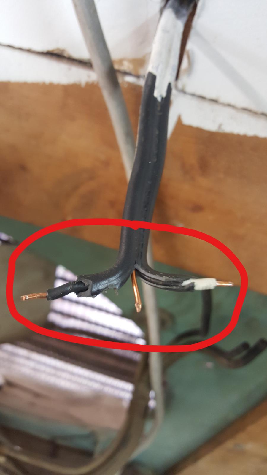
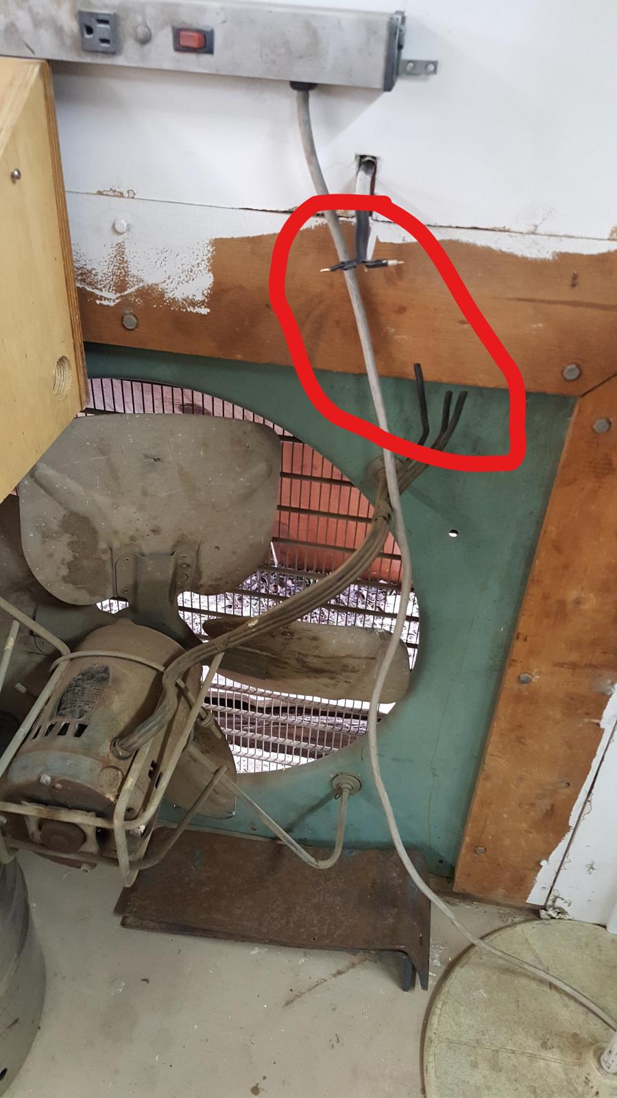
There is also an old attic style fan that was used as a cooling or exhaust fan to the shop on the far wall, and a much better location for brewing plus ventilation through the wall. The motor is rated for 230vac, so I'm thinking just add the appropriate receptacle there. The motor is seized up and bad anyway. When I measure the voltage on those wires I get 120vac to ground on both but when I measure across I don't get 240vac like I would expect, I only get a few volts, why is it not 240v like on the other circuit? It is also on a double 30 amp breaker which are tied together with a bar. In other words, you have to switch both at the same time in breaker box. Thanks and sorry for the long winded post, just trying to get a handle on this electrical stuff and any help would be much appreciated.
Cheers,
Matt...
 
First question,
There is a old slanted three prong cloths dryer receptacle. I measure voltage from ground to both blades and get 120vac on each and 240vac accross the two. It is on a 50 amp breaker. Shouldn't that be a 30 amp breaker? I believe that style receptacle is only rated for 30 amps correct?
The breaker should be whatever size it needs to be to protect the wires connected to it, not the receptacle or appliance connected to that circuit.

This plug is also not in the ideal location for brewing but could work in a pinch. I would need to run an extension cord from it.

Second question,
There is also an old attic style fan that was used as a cooling or exhaust fan to the shop on the far wall, and a much better location for brewing plus ventilation through the wall. The motor is rated for 230vac, so I'm thinking just add the appropriate receptacle there. The motor is seized up and bad anyway. When I measure the voltage on those wires I get 120vac to ground on both but when I measure across I don't get 240vac like I would expect, I only get a few volts, why is it not 240v like on the other circuit?
Because something isn't right.

It is also on a double 30 amp breaker which are tied together with a bar. In other words, you have to switch both at the same time in breaker box. Thanks and sorry for the long winded post, just trying to get a handle on this electrical stuff and any help would be much appreciated.

Measure across the two wires on the breaker in the box. Please be careful. Whilst doing that note the colors of those wires. One should be black and the other red. If you verify that there is 240 V across the breaker wires then obviously there should be 240 V across those wires at the other end. Be sure you are measuring between the right wire pairs at the fan end.

At this point we'll await your findings before commenting further.
 
Okay did some digging and came up with this...

The 50 amp breaker is feeding the dryer plug with 6g wire. That should be fine. :D

As for the fan wiring IDK. :confused:

The wire is standard house wiring "3 wire" black white and bare copper.
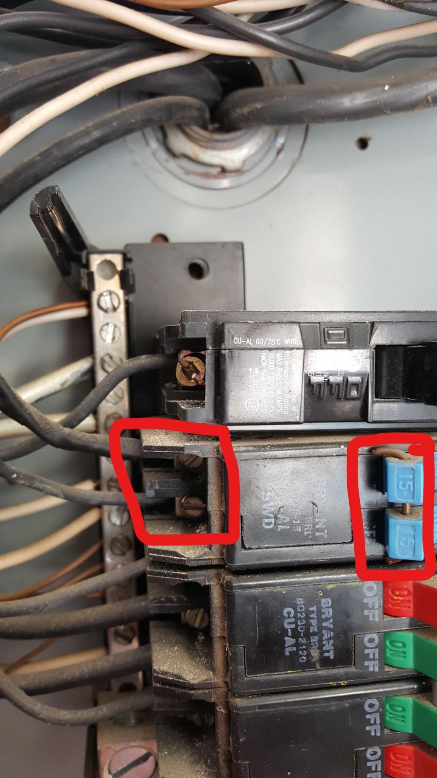
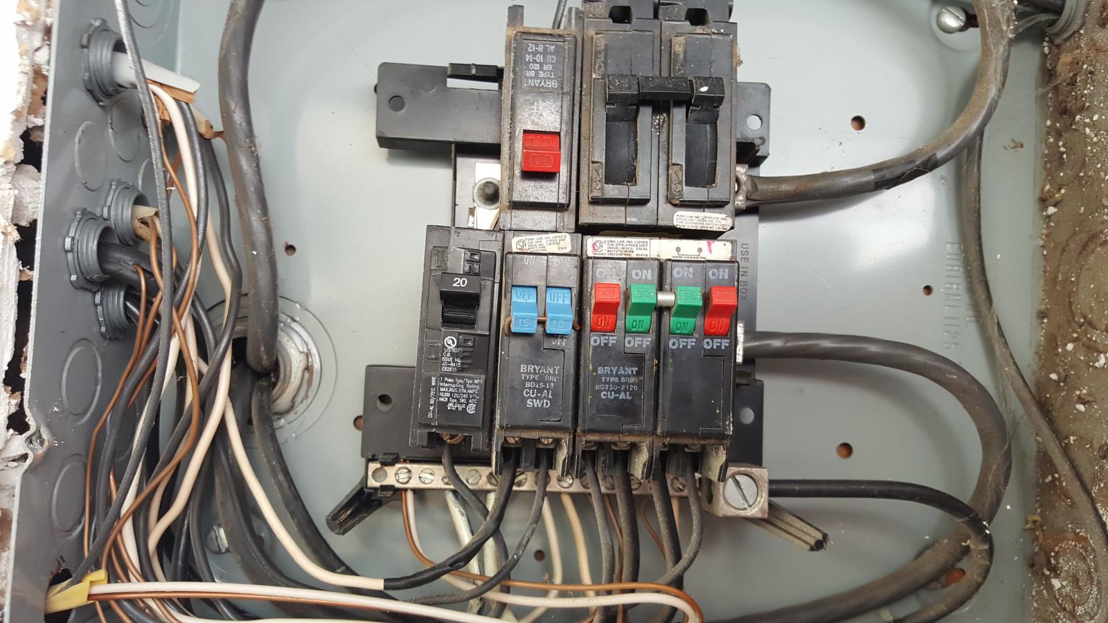
I was wrong about the breaker in the OP. It is a double 15 amp with the switches tied together. In the panel the white wire has black tape on it and is connected to the hot side along with the black wire. That is why I get 120v on both white and black wires to ground. Still don't understand how I still don't get 240v across the two? Same for at the breaker side. Is it because the breaker was never built to hook up that way and a different breaker might. Even though I don't think one would want to draw that much current through that type of wire. Any thoughts or suggestions? :confused:
Thanks again,
Matt...

20170207_110631_LI.jpg


20170207_110800_LI.jpg


20170207_110820_LI.jpg
 
The reason that you are not getting 240v on both lines at the fan is because that breaker is not designed to provide 240v. It is designed to provide 2x 120v circuits. The breaker is only tied to a single phase in the panel, and therefore both the black and white wires are providing the same source of voltage, essentially just doubling up on the conductors. Whoever made that modification clearly did not know what they were doing.

You really should use the dryer plug, with at least a 10awg extension cord with the appropriate ends. The wire going to that fan is not big enough to handle the amperage that a 5500w heating element would draw.

Also, you really should look into getting an electrician to look at all of this. If you take on this challenge by yourself, things can go bad very quickly, and even end in death or burning your house/shop down.
 
The wire is standard house wiring "3 wire" black white and bare copper.
I was wrong about the breaker in the OP. It is a double 15 amp with the switches tied together. In the panel the white wire has black tape on it and is connected to the hot side along with the black wire.
So far everything looks normal for a 240 V circuit. When a 2 conductor cable with a white wire is used for 240 the white wire must be marked with colored tape at both ends to indicate that it is not a neutral (grounded) conductor but a phase (ungrounded) conductor. I'm a bit on alert here because it is normal to use red tape for this to distinguish this wire from the black conductor in the cable and if the two are measuring the same volltage on both and 0 volts between that seems to suggest that they are connected to the same phase.

That is why I get 120v on both white and black wires to ground. Still don't understand how I still don't get 240v across the two? Same for at the breaker side.

Does this mean that if you put your voltmeter across the two screws on the breaker that you measure 0? This should not be as the picture shows what is, in my experience at least, always a breaker intended to contact both bus bars in the panel with the result that there will be 240 V between those two screws. Now it is possible that tandem breakers are made that only contact one of the bus bars and supply two branches tied together from a single phase. I've never heard of such a thing but then I'm not an electrician. It is simple enough to check out. Simply pull the breaker out of the panel (Main OFF) and see. If there are two prongs, fingers, grabbers, probes... or whatever then it is a normal breaker and the mystery runs deeper at this point. If there is only one then you have an unusual 2 pole breaker and your path to success is to simply replace it with a normal biphase (240 V) breaker of the same current rating.

Something is still fishy here because you said the circuit fed a 240 V load. Why would someone send parallel (same phase) 120V circuits to a 240V load? How would the current return? Certainly no competent person would use the ground wire for that but then you never know what a previous handy homeowner might have done. I know one guy who went into his attic to check on something shortly after moving into a new house and based on what he saw got his family out of the house.

So please verify that you are observing 0 V between the two screws on the breaker.
 
I do know attic fans will run on 120v or 240v on a two way switch. Kind of a low and high speed thing. I have never seen this fan run but then again it probably couldn't the way it was hooked up. I guess I'll just use a long extension cord and the 50 amp 240v dryer connection. I may use that existing wire to add a couple 120v receptacles on that wall since there is no other power in that part of the shop. Any thoughts on that?
Thank again,
Matt...
 
So far everything looks normal for a 240 V circuit. When a 2 conductor cable with a white wire is used for 240 the white wire must be marked with colored tape at both ends to indicate that it is not a neutral (grounded) conductor but a phase (ungrounded) conductor. I'm a bit on alert here because it is normal to use red tape for this to distinguish this wire from the black conductor in the cable and if the two are measuring the same volltage on both and 0 volts between that seems to suggest that they are connected to the same phase.


Does this mean that if you put your voltmeter across the two screws on the breaker that you measure 0? This should not be as the picture shows what is, in my experience at least, always a breaker intended to contact both bus bars in the panel with the result that there will be 240 V between those two screws. Now it is possible that tandem breakers are made that only contact one of the bus bars and supply two branches tied together from a single phase. I've never heard of such a thing but then I'm not an electrician. It is simple enough to check out. Simply pull the breaker out of the panel (Main OFF) and see. If there are two prongs, fingers, grabbers, probes... or whatever then it is a normal breaker and the mystery runs deeper at this point. If there is only one then you have an unusual 2 pole breaker and your path to success is to simply replace it with a normal biphase (240 V) breaker of the same current rating.

Something is still fishy here because you said the circuit fed a 240 V load. Why would someone send parallel (same phase) 120V circuits to a 240V load? How would the current return? Certainly no competent person would use the ground wire for that but then you never know what a previous handy homeowner might have done. I know one guy who went into his attic to check on something shortly after moving into a new house and based on what he saw got his family out of the house.

So please verify that you are observing 0 V between the two screws on the breaker.

As a former professional electrician (still practicing) I have never seen a tandem breaker that fits in just one slot touch two phases. All of the tandem breakers that include a 2 pole breaker have to, in my experience, take up two panel spaces to get both phases. on those breakers, there is a total of three circuits, and some times two 240v circuits. I will google that brand that is on the breaker, but I dont think that it is supposed to provide 240v. Also, they have made it a 2 pole breaker with a copper wire, and that is very suspect.

EDIT: After googling that brand of breaker, it looks like it is an Eaton/Cutler Hammer type BD breaker. That specific breaker is two circuit breakers on the same phase.
 
I do know attic fans will run on 120v or 240v on a two way switch. Kind of a low and high speed thing. I have never seen this fan run but then again it probably couldn't the way it was hooked up. I guess I'll just use a long extension cord and the 50 amp 240v dryer connection. I may use that existing wire to add a couple 120v receptacles on that wall since there is no other power in that part of the shop. Any thoughts on that?
Thank again,
Matt...

That circuit that feeds the fan needs to be rewired at the panel if it is to be used. As is, the return path is the ground wire (bare copper), which is absolutely not allowed, as it is a current carrying conductor. If you move the taped up white wire to the neutral buss in the panel, it will become a 120v circuit capable of either 15a or 20a depending on the wire gauge.
 
That circuit that feeds the fan needs to be rewired at the panel if it is to be used. As is, the return path is the ground wire (bare copper), which is absolutely not allowed, as it is a current carrying conductor. If you move the taped up white wire to the neutral buss in the panel, it will become a 120v circuit capable of either 15a or 20a depending on the wire gauge.

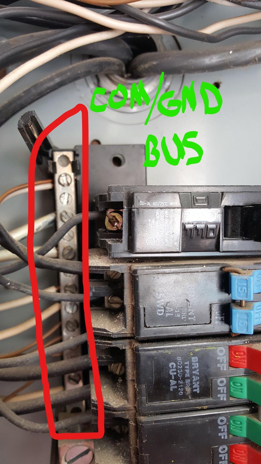
Thanks for the input, I think that is what I will do. Is the common bus and bare wire bus the same bus inside the box?
Thanks
Matt...
 
Sometimes they are, but usually in a sub panel (like an out building) they are kept separate. You would have to post a picture of the whole panel to determine that. Also, keep in mind that there is enough electricity in a panel to kill you. If you are smart and don't touch any electrified metal (bus bars, main lugs, etc) with your hands or un-insulated tools, you should be fine, but be careful.
 
Because of the two toggles I assumed those were two slot breakers and they clearly are not. Forget everything I said. Except that if it is a 120V circuit using the earth wire as neutral, it shouldn't.
 
Thanks for the input, I think that is what I will do. Is the common bus and bare wire bus the same bus inside the box?

Thanks

Matt...


If this box is the service entrance point yes. Neutral and earth must be bonded here. At any other point in the system (any sub panel) they must be kept separate.
 
Sometimes they are, but usually in a sub panel (like an out building) they are kept separate. You would have to post a picture of the whole panel to determine that. Also, keep in mind that there is enough electricity in a panel to kill you. If you are smart and don't touch any electrified metal (bus bars, main lugs, etc) with your hands or un-insulated tools, you should be fine, but be careful.


Neutral and earth MUST be bonded if the panel is the service connection point (indicated by a large breaker at top or bottom to which the service conductors are attached). In any sub panel they MUST be kept separated.
 
I hope you are aware that you should have a GFCI for protection before you start running 240v extension cords for brewing! Any water/electric operation will, by most codes that I am aware of, WILL require a GFCI!
Personally, I'd just look into the main box, and wire in a short run through the 2x4 stud to the next wall space (usually the main box will take up a 16" wide space between studs, but you should have some space next to it, or below it if necessary) - to a 50A or 60A spa panel (I think it was $60 at Lowes), go to Lowes or Home Depot and buy however many feet of 6 or 8ga wire you need to get from the main to your brewing space, and put a 6 or 8 space sub-box right where you are going to brew. Then you can run your 10ga wire from the breaker to the receptacle - I'd also encase all wiring in gray PVC electrical conduit if you run it outside the wall (if it's sheet-rocked or paneled), so that any little ankle-biters don't accidentally damage the wiring and light up like a neon sign! That way, if you want to brew all-electric in the future, you can add as many extra breakers as you need without re-wiring, (plus the spa panel IS your GFCI). This is what I've done in my mobile home and I don't even have any ankle-biters, BUT, I may want to sell in the future, and it makes things go much smoother if it looks like an electrician did the job!
just my 2 centavos worth ....
 
Last edited:
Hey guys,
A little update for you. I ended up moving the white wire over to the neutral buss, after removing the black tape, and installing a 110v receptacle in that wall by the fan. I will probably just use a standard box fan in the cut-out for ventilation if I need it. I like the idea of the spa panel being gfci. I was thinking about trying a gfci in the breaker box until I started pricing them. The spa panel seems to be a much cheaper option.
Thanks for all of the input I really appreciate it.
Matt...
 
I have come to the conclusion that I want to install a 50a spa panel in my shop/brewery with GFCI protection.
How can I tell if the panel in my shop is being treated as a main panel and not a sub panel of the house and just hooked up wrong?
The shop is a standalone building built in 1980 one year after the house was built.
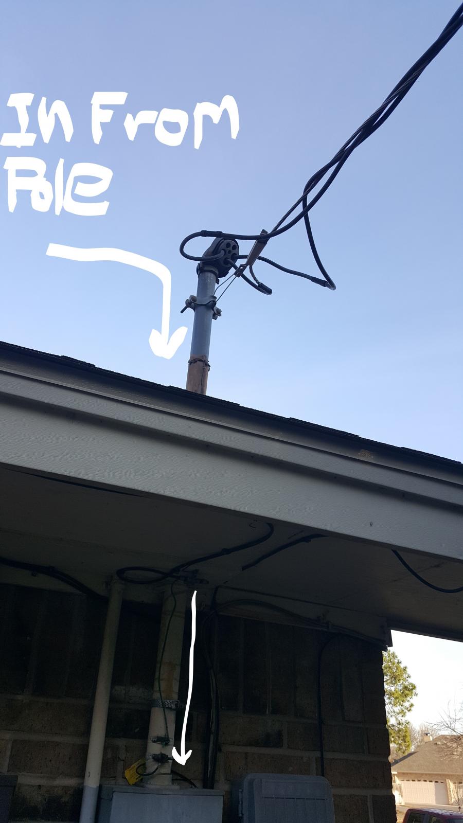
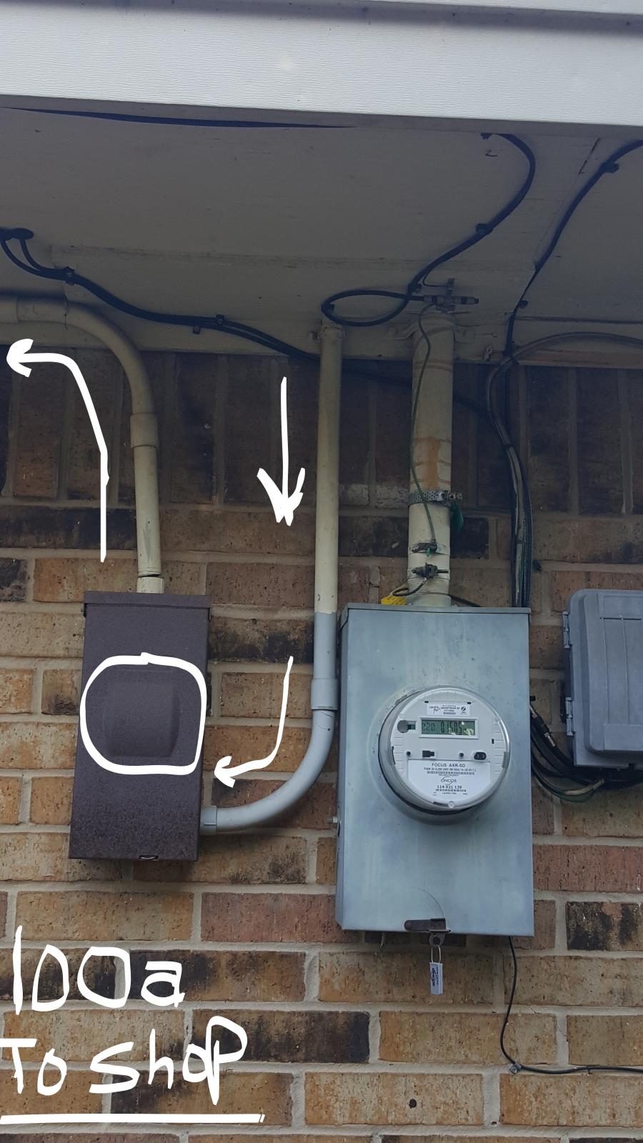
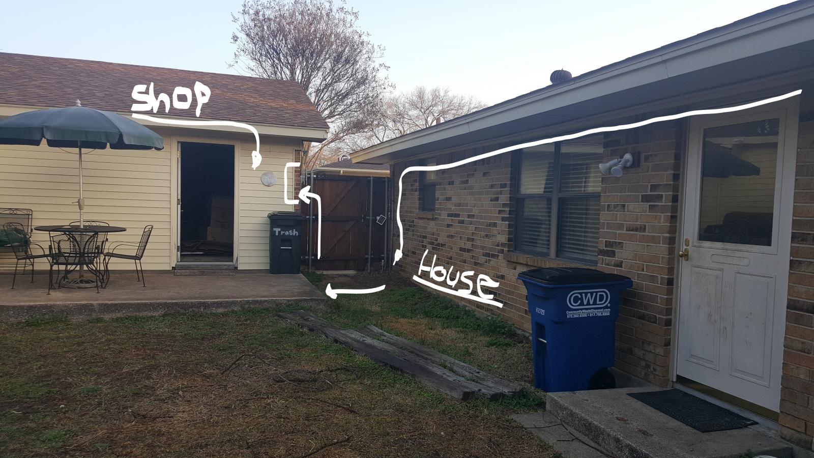
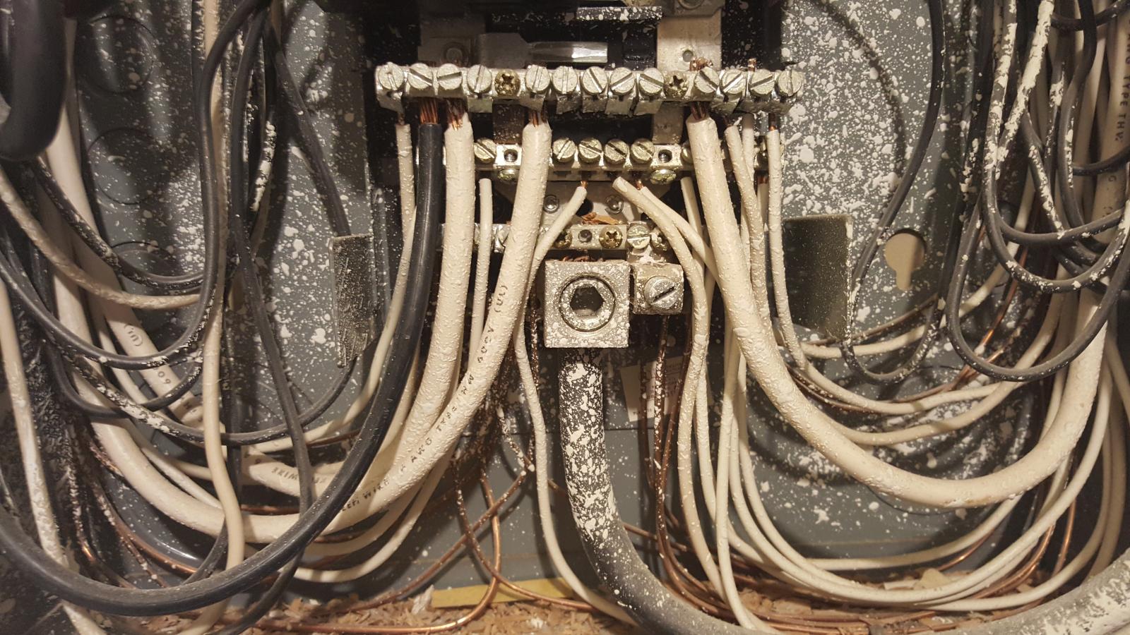
In the shop panel the "common" and "earth ground" are sharing the same bus, and I guess are considered bonded, which I believe is correct, so long as this is indeed a main panel. The breaker box in the shop is being fed from a smaller box on the side of the house with one 100a breaker in it. This is next to the house meter and overhead service lines. The conduit from the 100a box runs into the attic of the houses as well as the conduit from the meter. This is where I loose track of the run without climbing into the very back of the attic. The run from house to the shop is about 120 feet by guess. Pics are of the breaker box in the shop pointing out the 100a service into it and in fact the common and grounds are hooked to the same bus.
I understand that in the future spa panel I will need to keep the ground and common separate but want to be sure the MAIN BOX is a MAIN BOX first. I guess I could shut off all the circuits in the house and go see if I still have lights in the shop. :confused:
Any suggestions would be appreciated.
Thanks again,
Matt...:mug:

20170207_110631_LI (3).jpg


20170207_110706.jpg
 
The 100A breaker on the side of your house that turns off the shop is probably the service disconnect. The grounds and neutrals should be separated in your shop panel.

It looks like only a three wire feed to the shop too. Is the feed in metal conduit all the way from the house?
 
Your panel is definitely not the service entrance as there is no service disconnect in it. The 100 amp breaker at the meter would be the service disconnect. This is the only point at which your neutral and ground should be interconnected. From that point forward (towards the load side) you must run the two phases, the neutral and the grounding conductor (four wires). They must go to separate buss bars in any panel. Clearly you are not wired in this way and are, thus in violation of the code with the problem being that unless the loads are exactly balanced between the phases current will flow in the neutral and as the neutral has finite impedance the common bar in your panel will be raised to a voltage above ground potential as will the enclosures of any grounded appliances connected or plugged into outlets connected to this panel. There should be a separate grounding bar in your panel connected back to the ground/neutral bond at the service entrance holding your equipment enclosures at ground potential

Electricians apparently have trouble understanding this. I have done a couple of upgrades to electric service (one in Virginia) and one in Quebec. In both cases the electrician joined neutral and earth in the wrong place. In the Va case they did (or tried to do - the inspector caught it) just what has apparently been done in your case.

So what to do?

1) Pull a grounding conductor from the panel to the service entrance and connect it to a new bus in the panel which bus is bonded to the panel but isolated from neutral. Move all bare wires to this new buss.
2) Install an isolation transformer of appropriate size at the shop panel. Install a new ground rod at the shop panel. Connect a conductor from the ground rod and another from the center tap of the transformer to the common neutral/ground bar in the panel.
3) Do nothing and expect an occasional 'tingle' when you touch a piece of equipment in your shop.

Option 1) or 2) will get you right WRT to code AFAIK. But I don't think you will like the economics of either of them.

These are my musings based on what you have posted. You should get a professional electrician in to assess the situation but be sure you have one who understands grounding. How will you know that? Unfortunately the answer these days is to obtain a copy of the code (Amazon) and study it to the point where you can tell whether the electrician is giving you the right answer.
 
Good post as usual AJ. You're always so thorough. There may be an option 4 if the conduit is solid from the disconnect to the shop panel. If it is, it can be used as the equipment ground. Then he would only have to add a ground bar and separate the grounds and neutrals in the shop panel.

It's hard to tell but the feed conductors in the shop panel don't appear to be direct burial cable. That's not to say they aren't buried without conduit though.
 
Good post as usual AJ. You're always so thorough. There may be an option 4 if the conduit is solid from the disconnect to the shop panel. If it is, it can be used as the equipment ground. Then he would only have to add a ground bar and separate the grounds and neutrals in the shop panel.

Good point! Let's hope for OP's sake that this the case because the fix would be very reasonable compared to the options I suggested. Should be simple enough to see if the conduit is continuous with a current tracer.
 
The 100A breaker on the side of your house that turns off the shop is probably the service disconnect. The grounds and neutrals should be separated in your shop panel.

It looks like only a three wire feed to the shop too. Is the feed in metal conduit all the way from the house?

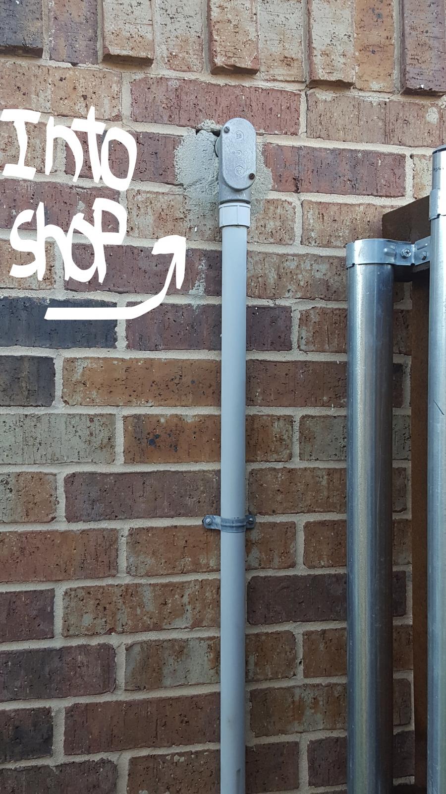
No, the conduit is PVC but appears to be continuous from house to shop. "See Pics"

"The 100 amp breaker at the meter would be the service disconnect."

No, the 100a breaker is in a separate box, not the meter. The run feeds the shop. I turned power off to the shop with it to work in the breaker box in the shop. The meter does not seem to have a disconnect switch unless it is under the little lock thingy? "See Pics"

"1) Pull a grounding conductor from the panel to the service entrance and connect it to a new bus in the panel which bus is bonded to the panel but isolated from neutral. Move all bare wires to this new buss."

So run a ground wire to a grounding rod in the ground to the service panel at the shop and add/connect to a ground bus. Then move all bare wires to it? Is this the 4th wire you speak of? If so, I think I can do that.

20170209_165357_Ink_LI (2).jpg


20170209_165422_LI.jpg


20170209_165456_Ink_LI.jpg


20170209_165606.jpg
 
It looks like the shop feed is probably taken from your main house panel or maybe a junction box and a tap in the attic? Is there another breaker in your house panel that you can kill the shop with?

It looks like it would be a bit of work to get a proper 4 wire feed to your shop. I probably wouldn't go to the trouble.
 
No, the conduit is PVC but appears to be continuous from house to shop. "See Pics"

So we can get the bad news out of the way up front: Ischiavo's suggestion is, unfortunately, therefore not possible. It would only be so were the conduit metallic.

"The 100 amp breaker at the meter would be the service disconnect."

No, the 100a breaker is in a separate box, not the meter.
That's OK. It can still be the service disconnect. The service disconnect isolates the load side of the building from the service conductors which are connected between the load side of the meter and the service disconnect. In a typical installation the power company installs a meter box on the outside of the house and the electrician runs conductors from the meter box to a panel or panels inside the house. Each of those panels has a MAIN circuit breaker which is the service disconnect for that panel. In this case the service conductors from the meter box are run to the box to the left and the breaker in there is thus the service disconnect (and current limiting means) for this building. Now the conduit to the meter box comes down from the soffit and the conduit to the disconnect box comes down from the soffit so the connection to the meter load side must be made somewhere up there and run back down through the conduit to the breaker box. This breaker box is the service disconnect point and it as at this point that the service neutral must be bonded to an earthing system which is usually a rod driven into the ground close to where the box is located. As there is no earthing conductor visible in this picture clearly your installation doesn't meet code. I see a skinny black wire running off to the right below the meter box. Does it go to a ground rod?


The run feeds the shop. I turned power off to the shop with it to work in the breaker box in the shop. The meter does not seem to have a disconnect switch unless it is under the little lock thingy? "See Pics"

I assume you house is serviced from another drop and has its own meter. Is this the case? It's pretty clear that this is the case from what I know and can see at this point and this implies that the 100A breaker is the service disconnect for this service.


"1) Pull a grounding conductor from the panel to the service entrance and connect it to a new bus in the panel which bus is bonded to the panel but isolated from neutral. Move all bare wires to this new buss."

So run a ground wire to a grounding rod in the ground to the service panel at the shop and add/connect to a ground bus. Then move all bare wires to it? Is this the 4th wire you speak of? If so, I think I can do that.

No. You are blending options 1) and 2). What appears to be needed, and I am saying "appears" because you really need to get a professional in to assess your situation - just not the 'professional' who installed this setup, is

A. Run a wire from the ground rod near the meter to the box with the 100 amp breaker in it and bond that wire to the neutral in the breaker box.
B. Pull a fourth conductor from the box with the 100 amp breaker to the panel.
C. Be sure that the common 'ground' buss bar in the panel is bonded to the mettallic parts of the enclosure. Remove all the branch circuits white wires from that buss bar.
D. Install another buss bar that is insulated from the metallic parts of the enclosure. Connect that bar to the the neutral from the box outside and terminate all the branch circuit white wires at that bar.

Looking at the panel photo I'm guessing that you are in the situation you are in because it is so archaic that it doesn't even have the separate buss bars meaning it was probably installed before the days when the code required the grounding conductor. I actually survived childhood in a house like that. It's electrical system stayed that way until it was torn down a couple of years ago. We just took the occasional tingle. You could choose to do the same.

If you choose to carry out the steps A - D above it would seem that the whole thing would be somewhat easier if you didn't have to modify the old panel. This suggests buying a new panel and that in turn suggest making this new panel the service entrance point. Buy a new 'Load Center' that contains a 100 amp main breaker. Drive a new ground rod as close to the location of the new panel as you can conveniently get it and run the grounding wire from that rod to the new panel. I'm not aware of any requirement on the length of run from the rod to the bonding point as long as the impedance to earth is < 25 &#937; (and if it isn't code only requires that a second rod be driven and is satisfied even in the combined impedance isn't < 25 &#937;). The 100 amp breaker in this panel now becomes the service disconnect and the new panel the point at which the earth/neutral bond is made. This all should be doable at appreciably less cost than A-D. You can leave the breaker in the box outside installed or you can take it out and splice the wires there. Be sure to use proper splices if you do this as the feeder wires are copper but the service wires may be aluminum.

I need to again emphasize that you should have an electrician do this work. I once got a Chinese Fortune Cookie fortune that read "Knowing how to do is easier than doing". I know how to do all this stuff and if you understand everything I put down here you know how to do it too. But you are best letting someone who does it for a living do it.

Making these changes will get you code compliant, belt and suspenders safe in you shop/brewery? Now how about you house?
 
The shop disconnect is not tied into the meter base. It has to be tied to something in the attic or to the main house panel. The outside disconnect may or may not be a service disconnect.
 
The shop disconnect is not tied into the meter base.
We don't know that. Obviously the load side wires from the meter run back up the visible conduit into the soffitt. What's up there I don't know. All we know from these pictures is that there must be an interconnection between the meter and wires to the breaker box. If there is another panel up there with a main breaker and the neutral is bonded up there to ground then that is the service disconnect point and four wires need to come down from that point to the breaker box and continue from the breaker box to the panel.


It has to be tied to something in the attic or to the main house panel.
As the service drop is here the hypothecated panel in the soffitt or attic would be the main panel and the house fed from that; not the other way around. As I don't see any aerial conductors besides the service drop wires and I don't see any other fat conduits dropping into the ground I have to assume that the house has its own drop. Around here (northern Virginia) utilities don't allow that but I know that in other places (Quebec) they don't care. Also I recognize that there may be runs inside the attic of this structure to other points from which conduits or aerial wires may depart to the main house in which case the service disconnect could be up there but that would violate the current (no pun) requirement that the service disconnect be easily accessible.

The outside disconnect may or may not be a service disconnect.
Certainly it is not one in terms of the current code because there is no earthing wire entering it.

At this point you and I are enjoying trying to suss out the situation from an incomplete picture which is challenging but OP really needs to get an electrician out to his place. To OP: keep sending pictures and we'll keep trying to figure it out and make appropriate suggestion. The important one's for now are:

How is your main house fed and (perhaps related) what's above that soffit (or in the attic)?

Exactly.

I am envisioning a panel inside the house fed directly through the exterior wall from the back of the meter socket. That is the way we usually do it. From that panel, possibly a feed into the attic which then drops out of the soffit and feeds the shop disconnect.

There are many ways it could be done. More pictures will help. I guess the fact remains that you will still only have a three wire feed to your shop.
 
Hey guys,
Thanks for you help as usual. I plan on climbing up and crawling all the way to the opposite side of the house and checking this out sometime this weekend. It is so hard to get back there. I am actually half afraid of what I might find. As far as the house goes the main house panel is not up to code either. The inspector told me it would have to be moved to an exterior wall and out of my master bedroom closet. It also needs to be replaced because it does not have a main breaker to kill "all circuits" which is a no-no too. And, code requires it to have "X" amount of space around it. So theoretically I can't hang cloths around it or use half of the closet. Yeah right...
Anyway, I really don't know if I can afford all of that at the moment. (maybe income tax)... I really just want to make beer again. ;)

PS... Oh and I already found a splice job in the attic for the exhaust vent over the stove. My thought was to fix with a junction box. I am not sure how much slack I will have for this type of repair though. I am afraid I might find more the deeper I dig, like the new fans in the two bathrooms I noticed??? :(

Thanks again,
Matt...
 
I am envisioning a panel inside the house fed directly through the exterior wall from the back of the meter socket. That is the way we usually do it.

I have been assuming all through this that all the pictures were of the out building. I admit to being a little puzzled as to why the telephone and cable services entered here as as to why the breaker box conduit goes up to under the eaves where the service comes in but enters the shop building via a conduit that comes up from below. I think the answer is that the first two pics must be the main house and the third the outbuilding.

There are many ways it could be done. More pictures will help. I guess the fact remains that you will still only have a three wire feed to your shop.

Assuming for now that there is a main panel behind the meter - if he could tap off the service wires before the main breaker and connect from that point to the black box with the 100A breaker, remove the breaker and jumper to the service wires he would now have service at the garage. If he replaced the old panel with a new one with a main breaker and connected a local ground to it he would have a separate service entrance for the garage. I can't find anything that says he can't do this with the exception that service to one building can't pass through another but if those wires passing through are in metal conduit then they are considered to be outside and OK.

He could also make the existing wiring a feeder but in that case he'd have to run a ground wire to the out building. Someone pulled the existing wires into that conduit so someone could, presumably, pull them out, add the ground wire and then pull them back in with lots of cable lube and swearing.
 
I have been assuming all through this that all the pictures were of the out building. I admit to being a little puzzled as to why the telephone and cable services entered here as as to why the breaker box conduit goes up to under the eaves where the service comes in but enters the shop building via a conduit that comes up from below. I think the answer is that the first two pics must be the main house and the third the outbuilding.

This is absolutely correct.
Sorry about that. I tried explaining that on the pics. Yes the first two pic are the main house and the third is where it goes into the out building. Further up the post are the pics of the panel in the shop and what is behind pic three.
Matt...
 
Hey guys,
Thanks for you help as usual. I plan on climbing up and crawling all the way to the opposite side of the house and checking this out sometime this weekend. It is so hard to get back there. I am actually half afraid of what I might find. As far as the house goes the main house panel is not up to code either. The inspector told me it would have to be moved to an exterior wall and out of my master bedroom closet. It also needs to be replaced because it does not have a main breaker to kill "all circuits" which is a no-no too. And, code requires it to have "X" amount of space around it. So theoretically I can't hang cloths around it or use half of the closet. Yeah right...
Anyway, I really don't know if I can afford all of that at the moment. (maybe income tax)... I really just want to make beer again. ;)

PS... Oh and I already found a splice job in the attic for the exhaust vent over the stove. My thought was to fix with a junction box. I am not sure how much slack I will have for this type of repair though. I am afraid I might find more the deeper I dig, like the new fans in the two bathrooms I noticed??? :(

Thanks again,
Matt...

It sounds like you have some electrical upgrades in your future. Not having a service disconnect for your house panel is not a good sign. Unfortunately, if you're seeing other sketchy wiring about, you'll probably find more.

I would plan for upgrades when money allows. Don't let it stop you from brewing though. Build your brewery well and plug it into your shop panel with a gfci in between. The brewery won't need to be changed when the wiring gets updated. A three wire feed doesn't meet today's code but if you do things right, it doesn't spell instant death.
 
Hi guys, I took some more Pic’s for all you voyeurs.
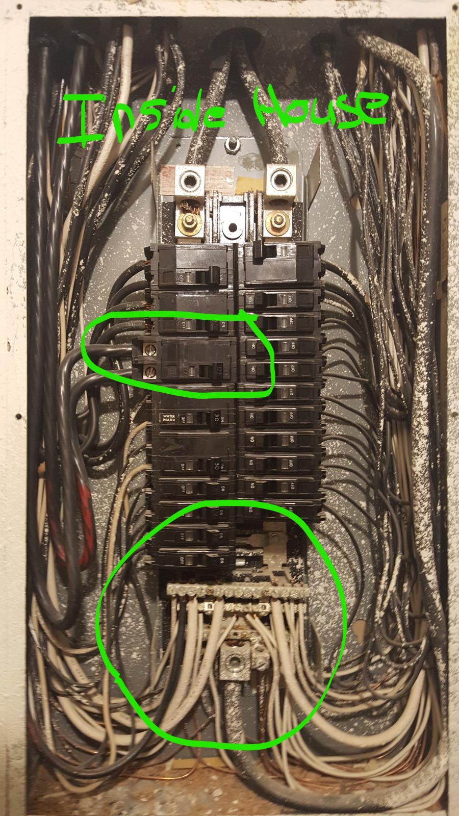
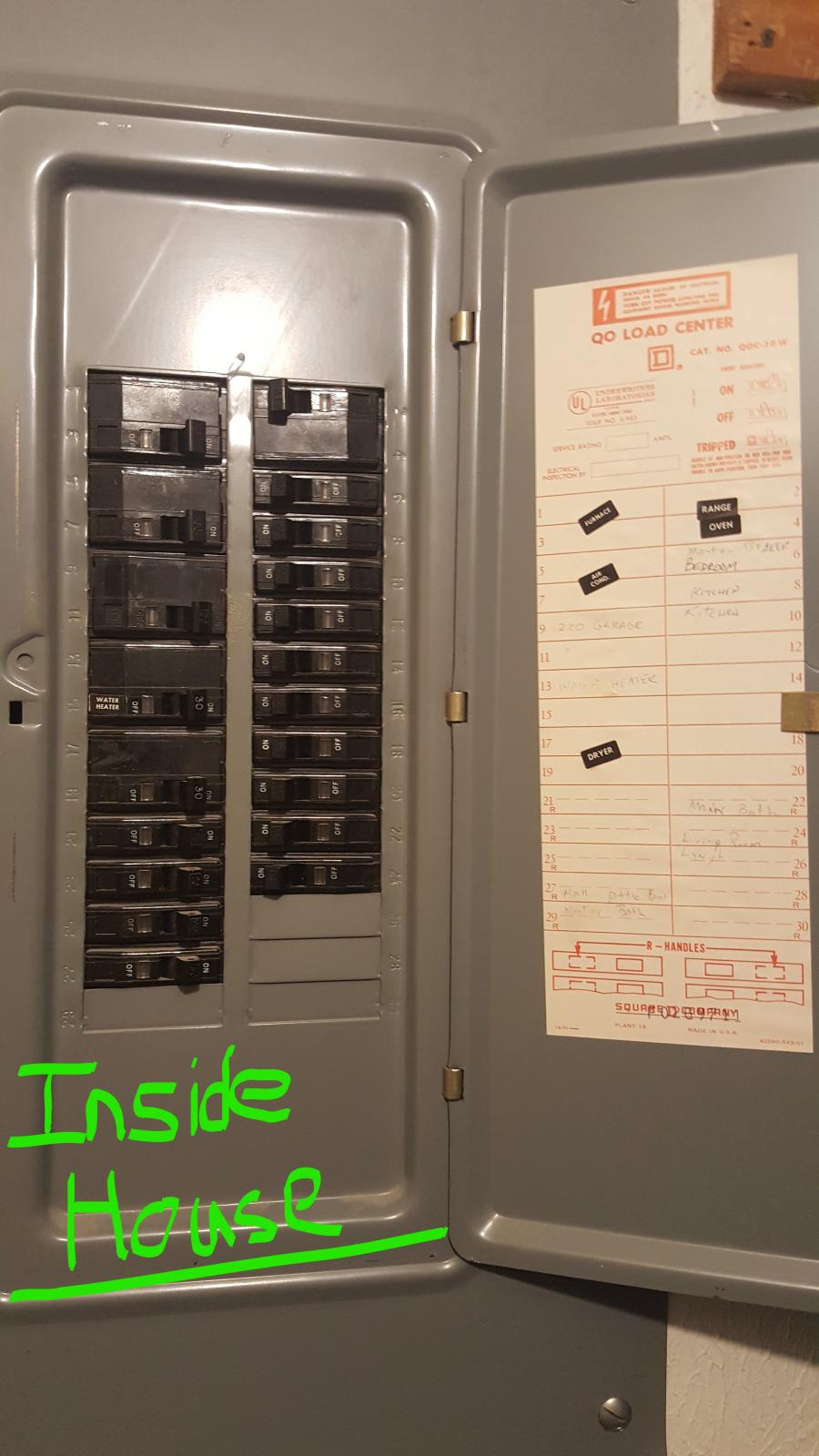
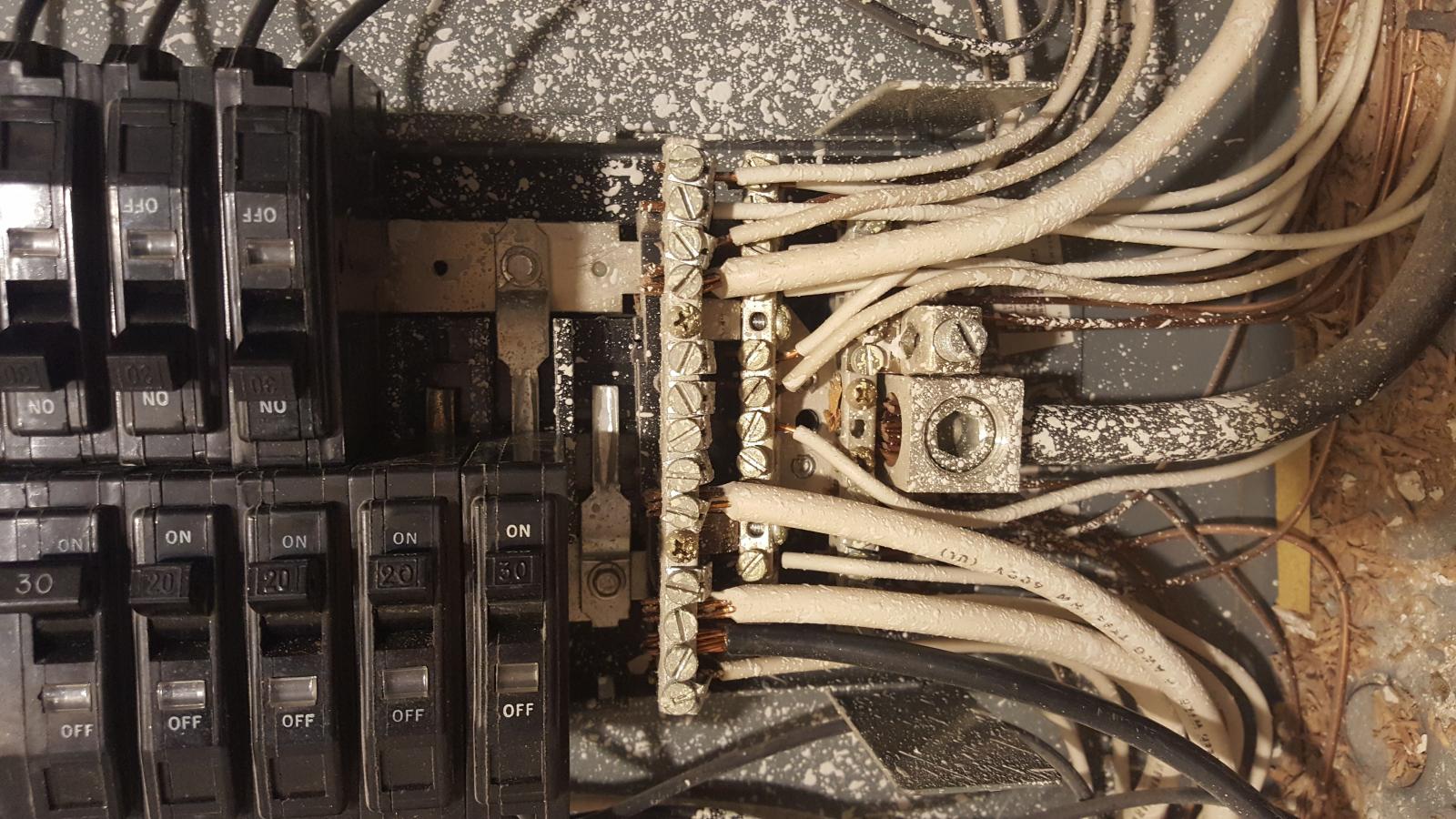
These are mostly pics of the inside house panel so you can see that aspect as well.
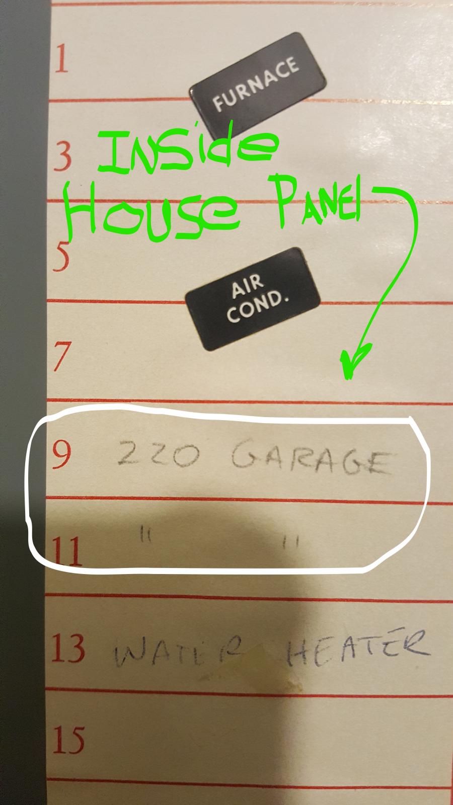
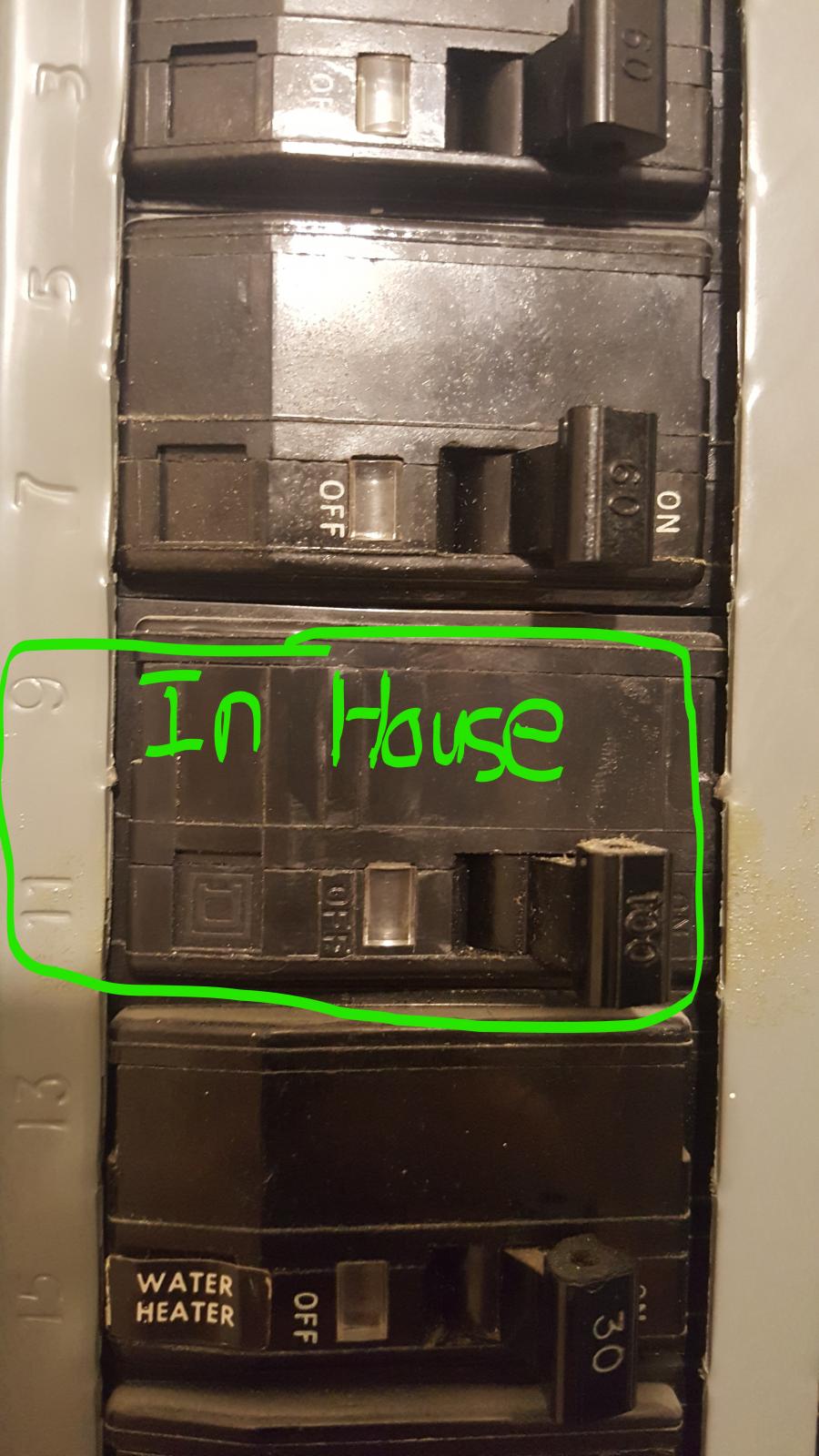
1. The panel inside the house looks newer then 1979 but I could be wrong, seems like it would have a main breaker but as you can see from the pic’s it does not.
2. The shop is fed with a 100a circuit breaker from the house panel. The feed runs to the small box w/ another 100a breaker outside as a service shutoff then about a 100’ run to the building.
3. I do not see any evidence of a grounding rod or any external grounding anywhere around the meter or box outside.
4. At least we know now that the house panel does feed the sub panel in the shop. The issue seems to be that it is a 3-wire feed with no isolated earth ground. (See 2 above).
Couple of questions:
1. With the setup in the shop being 3 wire, and the 50a receptacle being an old 3 prong slant dryer type connection, will a spa panel or an inline GFCI even be an option? I don’t want to spend money on a spa panel and just have it trip as soon as I apply power to it. Or worse yet, not protect the circuit and me… But I need GFCI protection
2. Can I try to earth ground the breaker box in the shop and isolate the common and earth ground with a ground bus addition, since it is a sub panel, right?
3. If so, I would assume a spa panel would be treated in the same manner, correct?
I can’t think of anything else right now so here are the pics…

20170211_075818_LI (2).jpg


20170211_084202_LI (2).jpg


20170211_084135.jpg
 
PS... I also have these pics too. but I guess there is a limit to how much you can up load at a time. (Keep Getting errors)

20170211_084557_LI (3).jpg


20170211_084603_LI.jpg


20170211_084548_LI.jpg


20170211_084015.jpg
 
3. I do not see any evidence of a grounding rod or any external grounding anywhere around the meter or box outside.

Just to the right of the lug for the neutral at the bottom of the main panel there is a smaller lug which I would guess is for the earth/ground. It perhaps goes to a rod driven into basement soil or perhaps to a water pipe. I'd check that out before concluding that there is no grounding system. There definitely ought to be one.
4. At least we know now that the house panel does feed the sub panel in the shop. The issue seems to be that it is a 3-wire feed with no isolated earth ground.
Yes. To feed the shop properly you need to run 3/3 from this panel to the shop panel.


1. With the setup in the shop being 3 wire, and the 50a receptacle being an old 3 prong slant dryer type connection, will a spa panel or an inline GFCI even be an option? I don&#8217;t want to spend money on a spa panel and just have it trip as soon as I apply power to it. Or worse yet, not protect the circuit and me&#8230; But I need GFCI protection
All GFCI does is make sure that the sum of the currents flowing in the two hots and the neutral is 0 which means that all current being delivered to a device is returned to the source through one of those three. If any current returns through any other path (such as you) the breaker will open.
2. Can I try to earth ground the breaker box in the shop and isolate the common and earth ground with a ground bus addition, since it is a sub panel, right?
Yes but what will you connect that bus to? It should be connected to the ground wire in the same panel. If that wire goes to a water pipe and the all the water pipes in your house are metallic and there is a water pipe in your shop then I suppose you could connect it to that.
 
Yes but what will connect that bus to. It should be connected to the ground wire in the same panel. If that wire goes to a water pipe and the all the water pipes in your house are metallic and there is a water pipe in your shop then I suppose you could connect it to that.

No water pipes in the shop.
I was thinking of an 8' grounding rod outside the shop running to the added bus and bus being mounted to the shop metal box. ???
Essentially grounding the box and all bare copper wires in it to earth ground and the commons would be isolated right?
See at the moment I only have one bus in the shop box with both common and bare wire hooked to it. I want to separate those and earth ground the bare wires, correct ?
Matt...
 
Just to the right of the lug for the neutral at the bottom of the main panel there is a smaller lug which I would guess is for the earth/ground. It perhaps goes to a rod driven into basement soil or perhaps to a water pipe. I'd check that out before concluding that there is no grounding system. There definitely ought to be one.

I wasn't concluding that there was no grounding system, simply pointing out it must be grounded somewhere. Maybe to the meter or pipes. Also no basement here in Texas. We just don't have them here.
I was hoping someone could reassure me the same assumption from the pics
of the breaker box in the house.
Thanks,
Matt...
 
No water pipes in the shop.
I was thinking of an 8' grounding rod outside the shop running to the added bus and bus being mounted to the shop metal box. ???
Essentially grounding the box and all bare copper wires in it to earth ground and the commons would be isolated right?
See at the moment I only have one bus in the shop box with both common and bare wire hooked to it. I want to separate those and earth ground the bare wires, correct ?
Matt...

I think that would be better than what you have. I'm not sure it meets code but I think you could argue that it is better than code as the ground potential under your feet when you are in the shop is more relevant to your safety than the ground potential under your house. I know that grounding when multiple buildings are involved is pretty tricky and I'm not sure that even the latest edition of the NEC reflects the best thinking on this subject.
 
I remember way back, some power companies wanted the grounding done in the meter socket it is possible that is how yours is done. I do not see a wire leaving your house panel that looks like it would head to ground rods or water piping.


I do see that it looks like no conduit is leaving the top of the panel for the incoming service conductors or the shop feed. I would assume then that those conductors are loose or maybe stapled up in your attic. That was never the proper way to do that. I'm really not sure how that service ever passed an inspection. Maybe it wasn't required in your area at the time.


A GFCI will function connected to your shop panel as is.
 
Back
Top