handbrewing
Member
Hello,
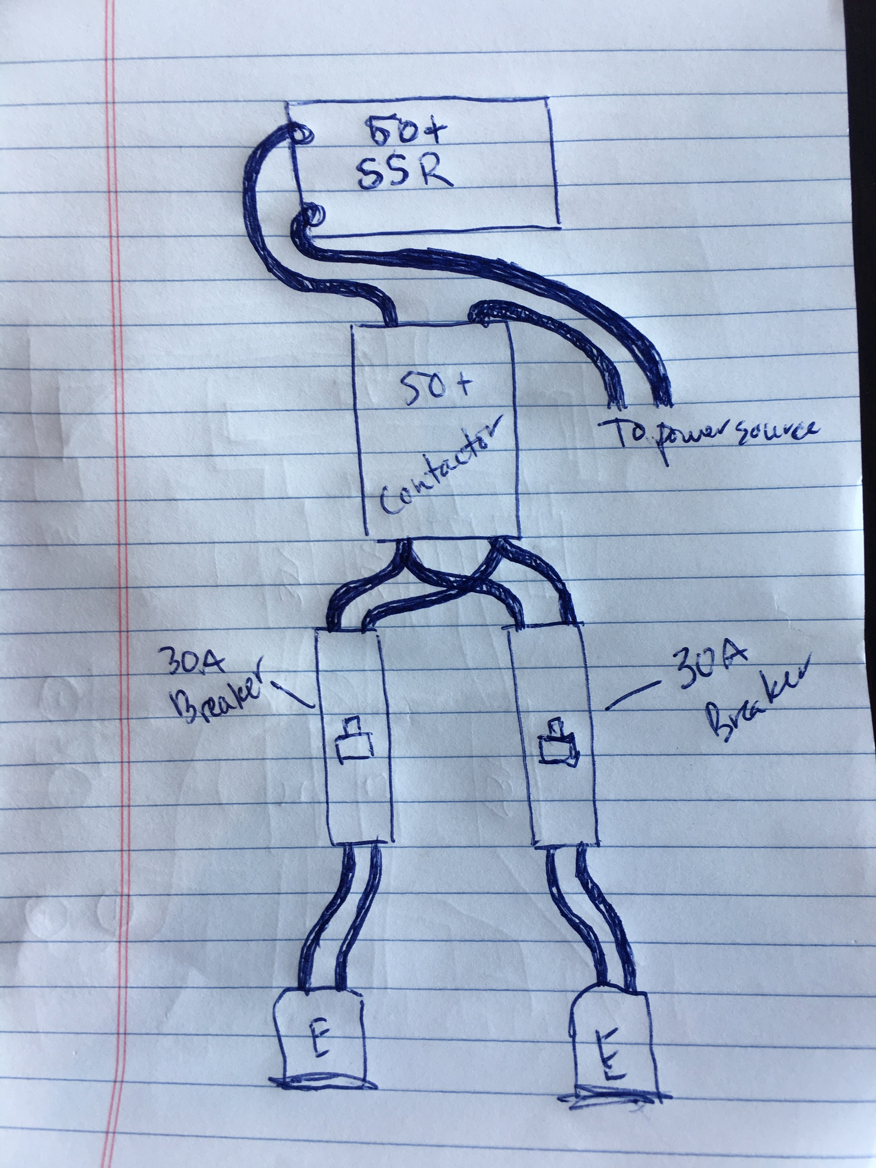
I've searched and couldn't answer my questions. I'm building a 1/2 barrel 2 vessel system. The 50a controller will have 1 pid to control 2 5500w elements simultaneously in the boil kettle with one switch to turn the elements on/off.
My question: Do I wire the elements through each contactor to each SSR the same as if I was using 2 PIDs like in the 50a back to back controller? My current thinking is the only wiring change would be from the PID to SSR's and switch to contactors. Is this correct?
Does anyone have a drawing for this setup?
50a
1 PID
1 on/off switch
2 5500w elements
2 Contactors
2 SSR's
I've previously built a 50a back to back controller with 2 pids controlling the elements independently but the move to 1 pid has me questioning things.