voltmeter/ammeter

Homebrew Talk - Beer, Wine, Mead, & Cider Brewing Discussion Forum

Help Support Homebrew Talk - Beer, Wine, Mead, & Cider Brewing Discussion Forum:

This site may earn a commission from merchant affiliate links, including eBay, Amazon, and others.

mendozer

Well-Known Member
Joined
Nov 15, 2009
Messages
766
Reaction score
19
Location
Seattle
so I want to put one of these on my CP

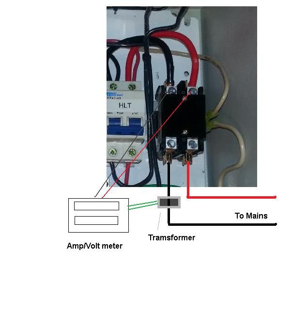
this description states it doesn't need any power additional. However, I'm using Kal's step by step instructions and he runs DC power supplies to power his (note his are separate ammeter and voltmeter)

how does this not need power?
 
Last edited by a moderator:
Correct - you don't need the AC/DC power supplies. It gets power from the AC voltage (up to 300V).

You put the little torroid (doughnut thingy) through the main HOT line and it uses that to measure current.

Both are easier than using a shunt as was done in my panel design. So why didn't I use something like this? I prefer the LED look (not LCD) to match the lights/PIDs/timer in my panel. So purely aesthetic.

Kal

Which wire from the control panel goes through the torroid?

Step 1) One of the screw input terminals to the HOT bus
Step 2) The other screw input terminal to the NEUTRAL bus
Step 3) Then, replace the 2" 10ga black wire (HOT A) running from the Power in twist-lock receptacle to the Power-In Relay (corner Labeled with a 1 on your Power Input Wiring Diagram located at http://www.theelectricbrewery.com/control-panel-part-2?page=7 ) with a 2' 10ga wire passing up through the torroid on the door and back down to the Power-In Relay?

or am I missing something?
 
I used a similar volt/amp meter too, and it works well. There is a wiring diagram in my gallery, linked in my sig.

Either I couldn't find the wiring diagram or we are talking about a not-so-similar volt/amp meter. It looks like the volt/amp meter in your diagram has four wired connections, rather than just two connections (Hot/Neutral) and another wire loosely passing through the 'donut' on the back.... Does yours also require external power?
 
So do both hot legs need to pass through the torroid in order to measure the total amperage drawn though the system?


Sent from my iPhone using Home Brew
 
Probably not. Assuming this system consists of a biphase (220 or 208V) heater plus some asymmetrical load such as a pump and that you wish to measure the current consumption of the heater only then one of the leads to the heater goes through the torroid. If you wish to measure the total consumption of the system it gets a little trickier because one of the phases carries the heater current alone and the other heater plus asymmetrical (pump) load current so that you must chose which you want to measure (or obtain a second current measuring channel). If you passed both phases (hot wires) in the same direction (i.e. from the source through the doughnut to the load) you would measure the difference between the currents flowing in them i.e. the phase imbalance. This could also be measured by passing the neutral alone through the toroid.
 
Either I couldn't find the wiring diagram or we are talking about a not-so-similar volt/amp meter. It looks like the volt/amp meter in your diagram has four wired connections, rather than just two connections (Hot/Neutral) and another wire loosely passing through the 'donut' on the back.... Does yours also require external power?


Here's a link to my build thread.

https://www.homebrewtalk.com/showthread.php?t=443594

Post 19 has several pics of the inside of the controller, and post 27 contains the wiring diagram. The two green wires are actually the ends of the single wire that is wrapped around the toroidal magnet (donut). The other two supply power and connect to the hot legs. As my controller is all 240V, there is no neutral.
 
you just need to. put through tooroid any one wire coming to your heating element. Doesn't matter if it goes through SSR or connected to receptacle directly from hot bus.
 
So I'm trying to make sure my meter shows everything on my panel on the display. So long as I run all my 110v on the same hot leg and pass that one through the torroid I should be fine then correct?
 
So I'm trying to make sure my meter shows everything on my panel on the display. So long as I run all my 110v on the same hot leg and pass that one through the torroid I should be fine then correct?

To get the full picture run the hot leg that serves the 120V loads and one side of the heater (joined on the load side of the torus) through the torus. Split the neutral (wire nuts) at the source side into two wires and run one through the torus and the other around it (i.e. not through it). Connect the neutral side of the 120V loads to the common terminal of a SPDT switch with each of the other two terminals connected to one of the neutral wires. With the switch connected to the wire that goes through the torus you will read the heater current plus the 120V load current. With the switch in the other position you will read heater current only.


Or you can run the neutral through the core and split the hot wire which feeds only the heater running one through the core and the other around it. Then the meter will display either the 120V load's current or the sum of the heater and 120V load currents depending on the switch position.
 
Cant remember who made this drawing using my setup but this is how its wired. Pretty easy actually. I need a visual to understand most this stuff sometimes!


box__zps7cbf993c.jpg
 

Latest posts

Back
Top