Simple Digital Brew Thermometer with Control Out

Homebrew Talk - Beer, Wine, Mead, & Cider Brewing Discussion Forum

Help Support Homebrew Talk - Beer, Wine, Mead, & Cider Brewing Discussion Forum:

This site may earn a commission from merchant affiliate links, including eBay, Amazon, and others.

rosienej

Well-Known Member
Joined
May 18, 2011
Messages
177
Reaction score
2
Location
Colchester
This thread is to document the build of a Digital Brew Thermometer.

Abstract:

I want a digital thermometer which can stand up to the demands of brewing.

Features:
1) Stainless steel construction
2) Battery powered and self contained.
3) Should be able to output 5 Volt control signals to turn on/off Solid State Relays
4) Alarm output

Current Design.

Mechanical:
1/4 Stainless Steel Cap. (McMaster Carr)
1/4 24 inch stainless steel pipe threaded both ends

Sensor
1) Analog Devices TMP03 MEMS based sensor (150 degree C max temp)

Processor+ display
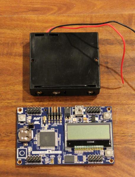
ATXMEGAA3BU-XPLD evaluation board (Mouser has these).

We will provide all of the code open source for non-profit use.

Please suggest features. I figure we need to be able to
1) set some target temps and dwell times,
2) 10 steps....
3) Identify the Action when a target temp is reached (Turn on output 1, set alarm etc...)

I have the parts coming in, and I have built two of the sensors, I will post pictures...

What do you think?

Joel
 
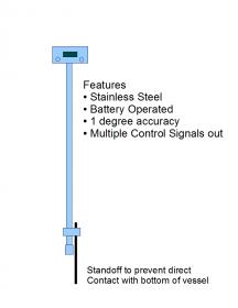
Here is the vision

BrewMeter.jpg
 
so you want a stand alone stainless steel PID?

I love the idea of a ready made thermometer capable of controlling SSRs but wouldn't the battery have to be substantial in order to do so over a long period of time, unless it was something you recharged after every brew?

I suppose you could integrate a rechargeable within the housing that gets trickle charged from the USB during usage.

Are the ebay temp controllers able to be powered via USB? perhaps a housing around one of those might work - can't remember if the can do SSRs or not.

I am interested in seeing how this develops.


I pulled a datasheet from opto22 and I get 3 volt operation draws 2 ma's, if I use 750ma/hr AA batteries (eneloops are 1.9Ahr) The TMP03 draws 1ma, and the processor is the biggest load.

I should be able to control multiple 3 hour mash cycles.
 
USB provides 5V, which would definitely be advantageous...

Yes, I could put in a charge circuit for the batteries if it is plugged in to USB.

I was thinking USB for the data-logging, but I could throw in a WiFi module, bluetooth or zigbee. The advantage would be no wires!!
 
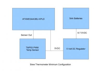
Here is a diagram of the basic system components. I am thinking of adding a XBee Wi-Fi Module so I can monitor the temps on any WiFi Enabled device (iPod, Android etc)...

Thoughts?

Joel

BrewMeter2.jpg
 
A4J said:
I would pay for this!

You can. You either know how to do it, or wait and see how he does it, and then buy the parts.

He also said he'd make his code freely available for personal use, so relax ;)
 
You can. You either know how to do it, or wait and see how he does it, and then buy the parts.

He also said he'd make his code freely available for personal use, so relax ;)

I am making sure all of the parts are off the shelf. Only basic tools will be required.

The hardest part will be finding a good looking water-proof case.

The electronics are on order, should be here soon.

Joel
 
For those who would like wireless temp. Monitoring with little or no custom software/hardware development. I will also show the following build.

1) MSP430 eZ430-RF2500 (Complete RF link to USB with temp demonstration software

2) Analog Devices Low Voltage Temp Sensor.

Parts on Order, when I get the parts I will do this build as well.

Pros: No case design at all.... should be all in one of the Home Debit stores
Cons: No Display on the sensor end, Need a USB port on the other end.

Rational: Have all the parts, and we can.
 
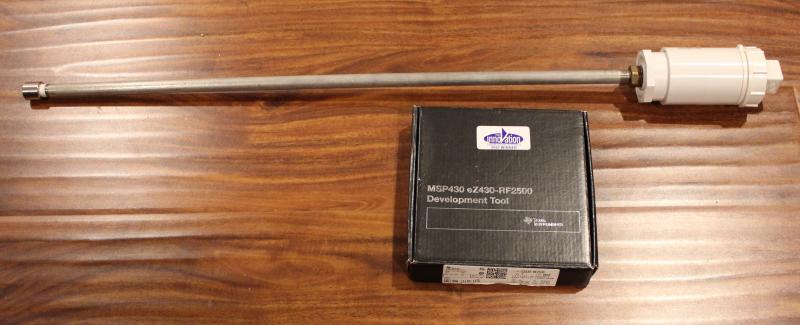
Here is the "Headless" version based on the TI MSP430 eZ430-RF2500 and a Analog Devices TMP35 [Not shown is the standoff on the bottom of the probe (I will strap a piece of wood to the probe with a hose clamp). For direct fired setups we need to keep the probe off the bottom, since the TMP35 (and TMP03) have a max temp of 150 degrees C.]

It will be a quick build while I am waiting on the parts for the LCD display version.

Joel

Headless1.jpg


Headless2.jpg
 
The XMEGA-A3BU Xplained is in....

Considering slight redesign, if I go with a ADC TMP35/TMP36 instead of the TMP03 (requires 5 Volts), I can get ride of a separate regulator if we can tolerate 3.3V switching of the Solid State Relays.

Also, I think I can power the XBEE WiFi Module without a separate regulator.

The NCP1117LPST33T3G regulator on the demo board is rated at 1Amp, and the XBEE needs 260mA transmitting.


Weekend looks like it will be busy...

Joel
 
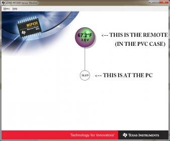
I put the ez430-RF2500 remote sensor in the PVC enclosure and I get approximately 20 feet range to the PC with no change to the PVC enclosure

I can always cut holes by the "chip" antenna and use some RF transparent tape... good enough for initial testing.

-Joel

FirstTest.jpg
 
The first image is the internals for the Headless, eZ430-RF2500 unit.

1) I am planning on using 4 AAA Batteries
2) Switch Power on switch is mounted on the top of the unit
3) Since I am using eneloop batteries, will have 4.8 volts nominal, so I am throwing in a 3.3 Regulator + cap (sorry), but it will make things more reliable.

The second image is the full-up WiFi unit with a simple step controller.

Things to do
1) Flip around the headers to the back, so I can close mount the unit to some clear plastic...
2) Pick up the XBee and mount the mess by the 4 AA batteries on the back.
3) Still debating if I need 3.3V Reg for the XBee and sensor.... hope not, might add later.

InternalsHeadless.jpg


InternalsSansWifi.jpg
 
Alternately... I have been thinking about a similar control option for a Fermentation vessel. Something that would plug thru a Carboy Cap with the 2 ports, or could be stabbed thru a drilled stopper. Whatever could be sealed. just a small narrow probe, with 2 wires. That could be wired to electronics such as you mention. I envisioned a cane shaped averaging probe that could measure the fermenting liquid. Or in the case of a mash bucket, hung on the sides (the reason for the cane).
 
Alternately... I have been thinking about a similar control option for a Fermentation vessel. Something that would plug thru a Carboy Cap with the 2 ports, or could be stabbed thru a drilled stopper. Whatever could be sealed. just a small narrow probe, with 2 wires. That could be wired to electronics such as you mention. I envisioned a cane shaped averaging probe that could measure the fermenting liquid. Or in the case of a mash bucket, hung on the sides (the reason for the cane).

Good idea.
 
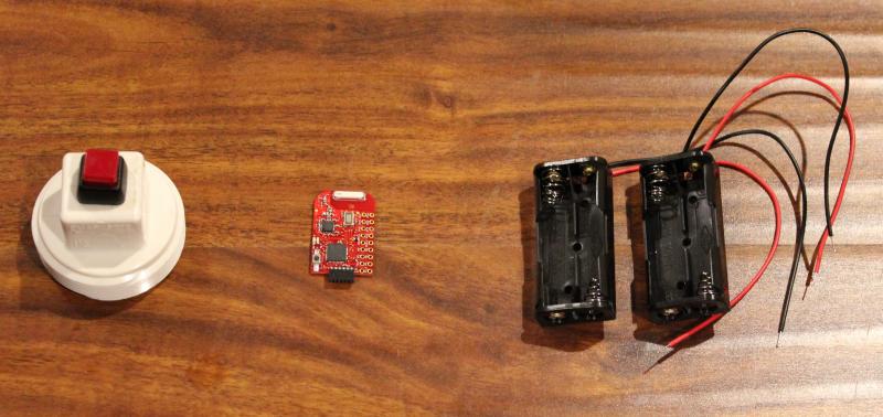
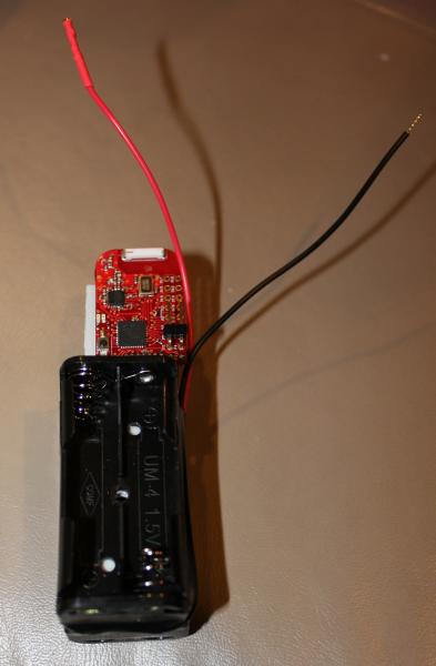
The image shows the internals of the "Headless" brewmeter.

I used two AAA battery holders, wired in series with a piece of plastic in the middle which extends above the holders on which the ez430-RF2500 is mounted using some Velcro or sticky tape.

I forgot to grab some 3.3Volt regulators so this part of the build will finish up on Monday.

I downloaded all of the tools from TI and the example project. Looks like we need to change two lines of code to finish the project.

I love it when I don't have to think !!

:)

Guts.jpg
 
1) ez430-RF2500, $50.00 + shipping from digikey
2) Pipes + Enclosure (Copper + PVC $20.00, Stainless +pvc $35.00
3) Sensor+Supporting electronics, $20.00

So I am in it for $105.00. Not cheap, but for a one-off....


Joel
 
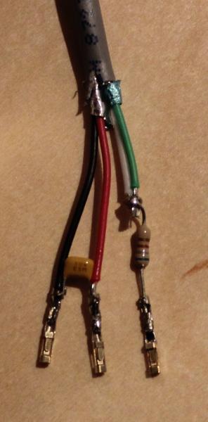
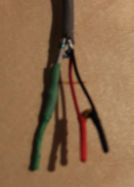
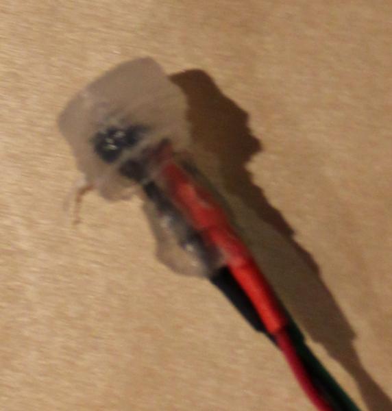
Step 1: Put on the 0.1uF bypass cap on the wires, and the series resistor as in the datasheet. I find using 0.100 square post fit the TO-93 leads well.

Step 2: Put on the heat shrink

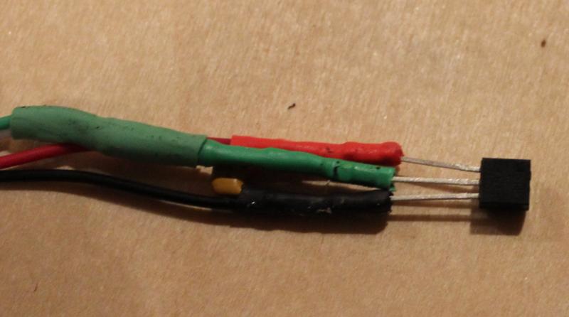
Step 3: Put on the sensor Check the datasheet, but when viewed from the bottom with the flat side up, +V, Sensor Out, Gnd

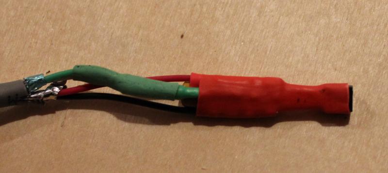
Step 4: Put on heat shrink to secure the sensor and the wires

Step 5: Put in Pipe

Step1 Componets.jpg


Step2 Shrink.jpg


Step3 Sensor.jpg


Step4 Shrink.jpg


Step5 Put In Pipe.jpg
 
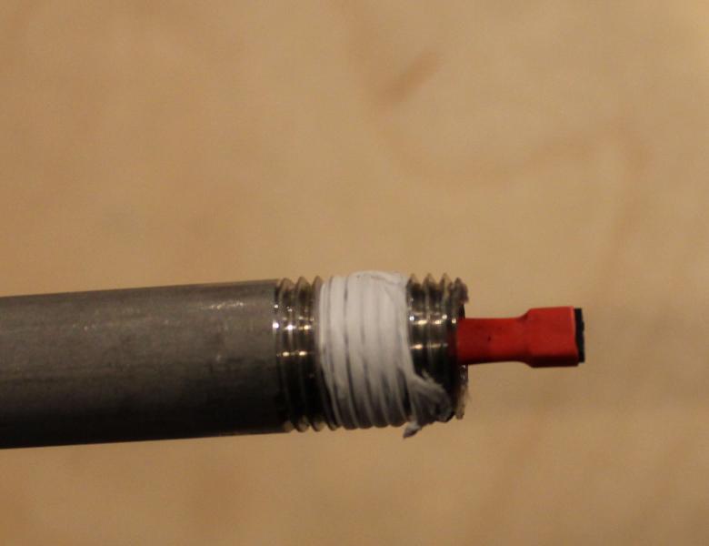
Step 6: Fill the cap with Silicone
Step 6a: Example of another sensor I pulled out of a pipe with the silicone (dried) on the sensor

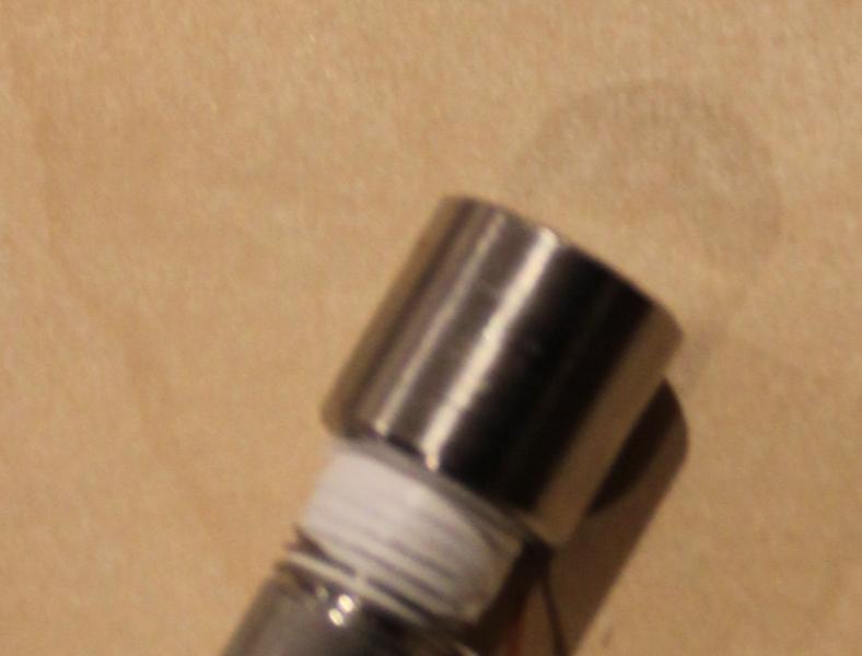
Step 7: Put on the cap.

Step6 Fill Cap With Silicone.jpg


Step6a Different Sensor Ex.jpg


Step7 Capit.jpg
 
This is the documentation

http://www.ti.com/lit/ug/slau144i/slau144i.pdf

Here are the CORRECT changes.

OLD Line 223: ADC10CTL1 = INCH_10 + ADC10DIV_4;
Change to
OLD Line 223: ADC10CTL1 = ADC10DIV_4;

LINE 255 Change to:
ADC10CTL0 = SREF_1 + ADC10SHT_3 + REFON + ADC10ON + ADC10IE + ADC10SR + REF2_5V;

Add after Line 225 a new line to select the external pin
ADC10AE0 |= 0x01

And change the formula to (Line 255) from
OLD LINE 255: degC = ((temp - 673) * 4230) / 1024;
to
NEW LINE 255: degC = (temp*2500)/1024;

Had to change 3 Lines and add one :)
 
You should use one of the Chronos kits for your user interface to the headless version. I have one sitting on my desk in the "to be tinkered with" stack, and it gives you a lot of options.

I was originally headed down this path for controlling my brewery. I even had some pic-based boards made up for temp control (16x2 LCD, heating and cooling circuits, knobs for setpoint control, etc), but at the last minutes I was able to scrounge up some hardware from work to be able to put a legitimate off-the-shelf industrial controller in it. Regardless, it would be really cool to be able to use your watch to get updates from the brewery and control things.

As a bit of a side note though, I really like the TI microcontrollers. They did a great job of putting together simple examples that you can use to get 90% of the way on the first steps of your projects. The development software is free, the starter programming kit is between $5 and $50 depending on what bells and whistles you want, and it makes a really good starting point for embedded projects.

http://processors.wiki.ti.com/index.php/MSP430_LaunchPad_(MSP-EXP430G2)

Good idea on the watch... I will check into it.
 
If you are going to attempt this, use IAR Embedded, the sample project compiles with no problem. The CSS project from TI is a bit messed... The IAR Embedded compile is very clean and easy. I will document the steps.

I need to test and calibrate the system, but the headless unit works!! On too the Wifi unit!!

Joel
 
The headless unit based on the ez430-RF2500 is done.


Cost: $100.00

You can add 10+ sensors to the wireless network with no changes

Powered on 4 AAA batteries, Eneloops should provide us with 12+ hours before a recharge.

The TI driver simply dumps data to a com port the format is text
with sensor number, temp, voltage so easy to work with...


Onto the ATMEL version, which is the full up controller with display and control out, and with a WiFi option.

Send questions/Suggestions.

Joel
 
Can your controller have several channels to have an all-in-one controller for all your different brew needs? i.e. Fermentation chamber, Keezer, HLT, MLT, RIMS, etc... Would be NICE to have it all wrapped up in a central box.
 
Can your controller have several channels to have an all-in-one controller for all your different brew needs? i.e. Fermentation chamber, Keezer, HLT, MLT, RIMS, etc... Would be NICE to have it all wrapped up in a central box.


Should be able to support both physically connected sensors and output switches, and "virtual sensors" and "virtual switches" ones which are connected over WiFi.

The limiting factor on the physical is the number of analog inputs and outputs, and the limit on the virtual is the update rate of the system.

Fun.
 
I have selected the following for the first build.

1) ATMEL: XMEGA-A3BU XPLAINED $39.00
2) MicroChip: MRF24WB0MB/RM $29.00
3) Analog Devices: TMP35 $1.50

I will design a PCB to hold these components and make the design available, or we can do a group buy to lower the costs.

The board will support:

Up to 8 directly connected Analog Sensors
8 digital outputs, optically isolated (5 Volts) to drive solid state relays

In addition, the software will support "Virtual Sensors", and "Virtual Switches", through a simple UDP based messaging protocol.

Might as well do it right. Any other suggestions.
Joel
 
The Watch would need another build. It doesn't seem to work on the same frequency as the ez430-RF2500

Yah, the ez430-RF2500 target boards are 2.4GHz, but you can get target boards that are in the 868MHz and 915MHz frequencies that are based on a similar but slightly different chip. You can get them from Farnell, but there has to be a US supplier too...

http://uk.farnell.com/jsp/search/productdetail.jsp?sku=1642378&_requestid=132347

Then it would be a pin-for-pin swap of your current board that you showed in post #22. It's probably not high on your priority list, but I'm throwing it out there just so you know that it's still a viable option that wouldn't require a full hardware redesign.

Thanks. It would be nice to have the temps logged on the chronos-TI watches.
 
I have selected the following for the first build.

1) ATMEL: XMEGA-A3BU XPLAINED $39.00
2) MicroChip: MRF24WB0MB/RM $29.00
3) Analog Devices: TMP35 $1.50

I will design a PCB to hold these components and make the design available, or we can do a group buy to lower the costs.

The board will support:

Up to 8 directly connected Analog Sensors
8 digital outputs, optically isolated (5 Volts) to drive solid state relays

In addition, the software will support "Virtual Sensors", and "Virtual Switches", through a simple UDP based messaging protocol.

Might as well do it right. Any other suggestions.
Joel

good luck with the tmp35's. I found them to be very accurate on the breadboard but worthless soldered onto the end of a 5' cable. I got so much noise it was reading +/- 30 degrees F. I ended up buying one wire sensors and found them to work much better. Good luck.
 

Latest posts

Back
Top