Need help with LED indicator problem.

Homebrew Talk - Beer, Wine, Mead, & Cider Brewing Discussion Forum

Help Support Homebrew Talk - Beer, Wine, Mead, & Cider Brewing Discussion Forum:

This site may earn a commission from merchant affiliate links, including eBay, Amazon, and others.

SavageBrewer

Well-Known Member
Joined
Jun 20, 2012
Messages
56
Reaction score
7
I am building a E HERMS system using one of the schematics from P-J. I am having a problem with the element on indicator staying on. When the PID is not turning on the element the LED is dim. When the element is turned on the LED gets brighter. I think this might be a problem brewing on a bright day outside, being that it would be hard to tell if the element is on. Here is the schematic I am using and have added an indicator in it. Please help me understand if I am doing anything wrong. Thank you.
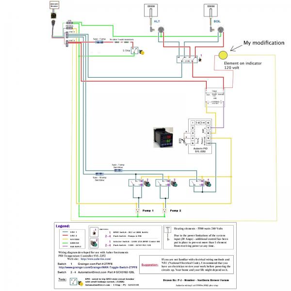
electricbrewingschematic1.jpg
 
The other side of the element circuit is still live and it's backfeeding the LED. The SSR is letting enough enough leakage current through to light it dimly.

You could do what I do and put a low voltage indicator on the control side of the circuit. It will indicate wether the control circuit is live but wouldn't show you if the ssr failed on. As you found already though it's not really working properly anyway though.
 
Maybe if I put a resistor between the LED and the SSR? I don't know. Just reaching here. I am kind of a perfectionist with things. I really want this to work the way I planned it. Thanks for the info. I appreciate it.
 
Maybe swap that 120v LED for a 240v, and put it across lines 1 and 2 right before the switch? I don't know if it will still light with leakage from the SSR, though.

Or if you're buying new LEDs anyway, go for a 12v DC LED and drive it off the SSR control lines. You'd have to check specs to see if that's possible, I'm just throwing ideas out there.
 
If you swap it to a regular bulb rather than an LED that will solve your problem as well. It can sink the leakage current and not glow.
 
SavageBrewer

First, Welcome to the forum. I hope you enjoy participating here.

I think your best option for an indicator light would be to use a 240V light similar to this setup. The light is placed on the load side and will only illuminate when power is applied to the element. If a single light is placed before the switch, it will also illuminate when the switch is in the center-off position. I suggest that you use 2 lights, one for each element.

As always - Click on the image to see a full scale diagram that is printable on Tabloid paper (11" x 17")


I hope this makes sense and helps you.

P-J
 
Thank you so much for all the help. A lot a thanks P-J. I appreciate all the work you do to help us homebrewers out. Just one question. Will the 240 volt let not light up with the leakage from the SSR? Again, thank you to all of you.
 
Thank you so much for all the help. A lot a thanks P-J. I appreciate all the work you do to help us homebrewers out. Just one question. Will the 240 volt let not light up with the leakage from the SSR? Again, thank you to all of you.
You are more than welcome.

If you place the 240V LED after the switch, it will not light with SSR leakage current. It will be connected in parallel with the heating element and any SSR leakage current will be shunted through the element instead of being available for powering the LED. This is also the reason that I suggest using 2 indicator lights so that there will not be any power available to the LED in the Center-Off position. The only way that I can think of to use a single LED and have it function as you would want, would be to add additional switch modules to the element control switch. That can be done but the cost for the added modules would far outweigh the cost of the second LED.

If you need a plan to do it that way, I'd be glad to help you in your adventure.

Wishing you the best,

P-J
 
P-J, I will just add a second LED. Luckily I left room on my control box for further upgrades, so I don't have to drill out a spot that will look out of place. Thanks for the help and the upgraded schematic.
 
According to the schematic P-J, what type if wire and what gauge should I use? Also, is automotive grade wire acceptable?


image-3572582782.jpg
 
According to the schematic P-J, what type if wire and what gauge should I use? Also, is automotive grade wire acceptable?
You need to use #10 wire for the 240V connection to the element switches, the element wiring and the 240V side of the SSR. The 120V wiring can be done using #14 wire. The wiring for the control circuits can be smaller if need be. I would not use auto wire as I have no idea of the rating of it.

BTW: Use stranded wire not solid conductor. This will make your set up much easier to handle.
 
Auto wire should be fine. It's usually just much finer stands of copper so it's more flexible. I think you were asking about what gauge to use for the new Led lights. If that is the case you can use as small as 18-20 gauge. The LEDs don't use much power at all.
 
I was wondering if auto wire can be used to wire all the parts inside the panel. The only reason I ask is cause I have a lot of it laying around.
 
I would not use auto wire as I have no idea of the rating of it.
I say this because I do not know. If I had it in hand I'd know.

Look at the wire and if you are comfortable using it, do it. I do not have any problems with that at all.

BTW: That is exactly what I would do in your situation with the wire in hand.

P-J
 
The wire will be used. I figure if it can handle oil, grease, water, and the high amps of automotive batteries I will use it. Thanks for the help.
 
Sorry if it's been some time since my last reply. I have another question for P-J. In the previous schematic in this thread the elements are 5500 watt elements. Unfortunately my kettles only fit 4500 watt elements. Should I still use 10 gauge wire for the 240 volt side?
 
Sorry if it's been some time since my last reply. I have another question for P-J. In the previous schematic in this thread the elements are 5500 watt elements. Unfortunately my kettles only fit 4500 watt elements. Should I still use 10 gauge wire for the 240 volt side?
You could. A 4500W element on 240V draws 19A. This means that you could use #12 wire (20A).

Me? I'd use the #10. But that's me.

P-J
 
5500w and 4500w use the same fitting. Are you saying you don't have them locally? Kettles will fit all of them equally.
 
I have a bayou classic 44 qt. kettle. I think the 5500 watt element is to long to fit. I have been told that the 4500 watt element at highgravity brew will fit my particular kettle.
 
P-J said:
You could. A 4500W element on 240V draws 19A. This means that you could use #12 wire (20A).

Me? I'd use the #10. But that's me.

P-J

I went with the 10 ga. wire anyways. All is wired now. Waiting on an electrician to install an outdoor outlet now.
 
Back
Top